


Chapter 6. Configuration
61202.029L2-1 ISU 128 User Manual 43
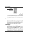
Connector Type
The ISU 128 can provide an EIA-232, RS-530, or V.35 interface to a DTE by se-
lecting the desired connector type.
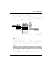
RTS Options
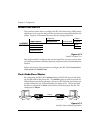
Selecting 1 MS delay causes the Clear-to-Send (CTS) signal to change states 1
millisecond after the DTE Ready-to-Send (RTS) signal changes state. The 18
MS delay causes the CTS signal to change state 18 milliseconds after the DTE
RTS signal changes state.
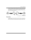
CTS Options
Selecting Forced CTS causes the CTS signal on the DTE connector to be con-
tinually asserted. Selecting Follows RTS causes the CTS signal to follow the
state of the RTS lead.
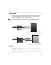
CD Options
Selecting CD Forced on causes the carrier detect (CD) signal to always be as-
serted. Selecting Normal causes the CD signal to be asserted when a call has
been successfully established. Selecting Off with LOCD causes the CD signal
to be disasserted for a period of 5 seconds, then reasserted at the termination
of a call. Selecting Off with Link Down causes the CD signal to be disasserted
when the U-interface is not present.
DTR Options
Selecting Ignore DTR causes the ISU 128 to disregard the state of the data ter-
minal ready (DTR) pin. Cmd when Off forces the unit into the AT command
processor mode when DTR is not asserted. To return on-line, DTR must be as-
serted, followed by the AT0 command. Idle when Off forces the unit to end
the current call when DTR is no longer asserted. Off>On dial #0 allows one
call attempt to be automatically established when the DTR signal goes from in-
active to active. While DTR is active, front panel dialing is also possible.
When DTR goes inactive, any outgoing call present is disconnected. Off>On
dial #0 uses the phone number in stored number register 0 to establish the call.
To store a number for automatic dialing see the chapter Dialing Options. Se-
lecting Dial #0 if On allows calls to be automatically established when the