


Chapter 2
Configuring the Agilent E1364A Form C
Switch
Using This Chapter
This chapter shows how to make user connections to the Form C Switch and
how to configure the switch module. Chapter contents are:
• Warnings and Cautions . . . . . . . . . . . . . . . . . . . . . . . . . . . . . Page 17
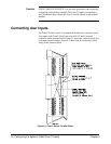
• Connecting User Inputs . . . . . . . . . . . . . . . . . . . . . . . . . . . . . Page 18
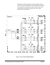
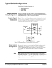
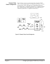
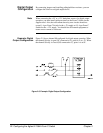
• Typical Switch Configurations . . . . . . . . . . . . . . . . . . . . . . . Page 20
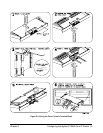
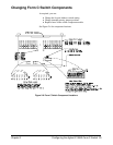
• Changing Form C Switch Components . . . . . . . . . . . . . . . . . Page 23
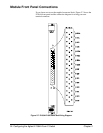
• Module Front Panel Connections. . . . . . . . . . . . . . . . . . . . . . Page 24
Warnings and Cautions
Warning SHOCK HAZARD. Only qualified, service-trained personnel who
are aware of the hazards involved should install, configure, or
remove the module. Use wire rated for the highest input voltage
and remove all power sources from the mainframe and installed
modules before installing or removing a module.
Caution MAXIMUM VOLTAGE/CURRENT. Maximum allowable voltage per
channel for the module is 250 Vdc or 250 Vac RMS (350 V ac peak).
Maximum current per channel is 1 Adc or 1 Aac RMS (non-inductive).
Maximum power input is 40 W (dc) or 40 VA (ac) per channel or 320 W
(dc) or 320 VA (ac) per module. Exceeding any limit may damage the
module.
Caution CONNECTING + 5V + 12V: On the module, the backplane + 5V line is
fused at 4 A and the + 12V line at 1 A. When connecting + 5V or + 12V to
the Form C Switch, install appropriate pullup resistors to prevent shorting
the power supplies. Also, the total current drawn by all circuits connected to
the Form C Switch must not exceed the fuse rating for the supplies used.
Chapter 2 Configuring the Agilent E1364A Form C Switch 17