


Typical Switch Configurations
Typical Form C Switch configurations are:
• General purpose relay
• Relay control
• Digital output
General Purpose
Relay Configuration
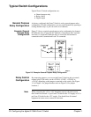
As factory configured, the Form C Switch is set for general purpose relay
configuration. For this configuration, you can switch channels by opening or
closing channel relays or you can scan a set of channels.
Example: General
Purpose Relay
Configuration
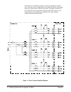
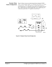
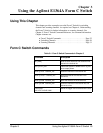
Figure 2-3 shows a typical general purpose relay configuration for channel
00. When the relay is open, the NC terminal is connected to the C terminal
and Load 1 is connected. When the relay is closed, the NO terminal is
connected to the C terminal and Load 2 is connected.
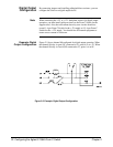
Relay Control
Configuration
By connecting jumpers, you can use the Form C Switch to drive (control)
external relays. The source can be +5V/NO, +5V/NC, +12V/NO, or
+12V/NC depending on the jumpers connected on the switch. (See Figure
1-1 in Chapter 1 for jumper numbers and see Figure 2-6 for jumper
locations.)
Note When connecting the +5V or +12V backplane sources, the total current
draw should not exceed 1 A per Form C Switch for the +5V supply or 0.5 A
per Form C Switch for the +12V supply. You should fuse all external
equipment to ensure excess current is not drawn.
Figure 2-3. Example: General Purpose Relay Configuration
20 Configuring the Agilent E1364A Form C Switch Chapter 2