


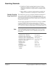
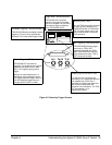

Scanning Channels
• For the Form C Switch, scanning channels consists of closing a
specified set of channels, one channel at a time. You can scan any
combination of channels for a single-module or a multiple-module
switchbox.
• Single, multiple, or continuous scanning modes are available. See
Chapter 4 for information on scanning Form C Switch channels.
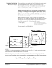
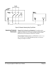
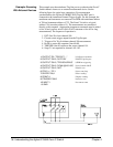
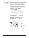
Example: Scanning
Using Trig Out Port
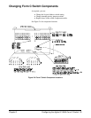
This example shows one way to synchronize instrument measurements of
devices under test (DUT) with Form C Switch channel closures. For
measurement synchronization, the Agilent E1300B/E1301B Trig Out BNC
port is connected to the instrument External Trigger In port. See Figure 3-6
for typical user connections.
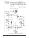
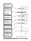
For this example, the mainframe and instrument are connected via GPIB to
an Agilent E1300B/E1301B mainframe with an address of 709 and an
external instrument (such as an Agilent 3457A Multimeter) with an address
of 722. The Form C Switch is at logical address 120 (secondary address 15).
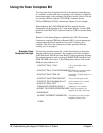
Note You must add required instrument commands to line 10. Also, you may
need to add a WAIT statement as line 65, depending on the speed of the
measurement.
10 OUTPUT 722; "TRIG EXT;.. " ! Ext triggering
20 OUTPUT 70915; "OUTP ON" ! Enable Trig Out Port
30 OUTPUT 70915; "TRIG:SOUR BUS" ! Bus triggering
40 OUTPUT 70915; "SCAN (@100:102)" ! Scan channels 00-02
50 OUTPUT 70915; "INIT" ! Enable scan
60 FOR l=1 TO 3 ! Start loop
70 ENTER 722:A ! Enter result
80 PRINT A ! Display result
90 TRIGGER 70915 ! Advance scan
100 NEXT I ! Increment count
110 END
Chapter 3 Using the Agilent E1364A Form C Switch 31