


Chapter 2 Initial Operation
Power-On Checkout
28
Power-On Checkout
The power-on test includes an automatic self-test that checks the internal
microprocessors and allows the user visually to check the display. You will
observe the following sequence on the display after pressing the front panel
power switch to on.
1 All segments of the display including all annunciators will turn on for about one
second.
To review the annunciators, hold down key as you turn on
the power supply.
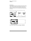
2 The GPIB address or RS-232 message will then be displayed for about one
second.
The GPIB address is set to ‘‘5’’ when the power supply is shipped from the
factory for remote interface configuration. If this is not the first time the power
supply is turned on, a different interface (RS-232) or a different GPIB address
may appear.
See "Remote Interface Configuration" in chapter 3 starting on page 56 if you
need to change the remote interface configuration.
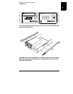
3The “
15V”, “OVP”, “OCP” and “OFF” annunciators are on. All others are off.
The power supply will go into the power-on / reset state; the output is disabled
(the
OFF annunciator turns on); the 15V/7A range is selected (the 15V
annunciator turns on); and the knob is selected for voltage control. Notice that
the
OVP and OCP annunciator also turn on.
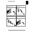
4
Enable the outputs.
Press the key to enable the output. The
OFF annunciator turns
off and the
15V, OVP, OCP, and CV annunciators are lit. The blinking digit can
be adjusted by turning the knob. Notice that the display is in the meter mode.
‘‘Meter mode’’ means that the display shows the actual output voltage and
current.
Note
If the power supply detects an error during power-on self-test, the
ERROR
annunciator will turn on. See "Error Messages" for more information
starting on page 121 in chapter 5
ADDR 05 (or RS-232)
Display Limit
Output On/Off
Output On/Off