


Chapter 3 Front-Panel Operation
RS-232 Interface Configuration
64
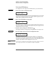
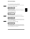
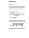
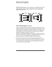
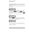
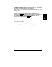
DB-25 Serial Connection If your computer or terminal has a 25-pin serial
port with a male connector, use the null-modem cable and 25-pin adapter
included with the Agilent 34398A Cable Kit. The cable and adapter pin
diagram are shown below.
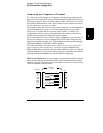
DTR / DSR Handshake Protocol
The power supply is configured as a DTE (Data Terminal Equipment) device
and uses the DTR (Data Terminal Ready) and DSR (Data Set Ready) lines of
the RS-232 interface to handshake. The power supply uses the DTR line to send
a hold-off signal. The DTR line must be TRUE before the power supply will
accept data from the interface. When the power supply sets the DTR line
FALSE, the data must cease within 10 characters.
To disable the DTR/DSR handshake, do not connect the DTR line and tie the
DSR line to logic TRUE. If you disable the DTR/DSR handshake, also select a
slower baud rate to ensure that the data is transmitted correctly.
The power supply sets the DTR line FALSE in the following cases:
1
When the power supply’s input buffer is full (when approximately 100
characters have been received), it sets the DTR line FALSE (pin 4 on the RS-
232 connector). When enough characters have been removed to make space
in the input buffer, the power supply sets the DTR line TRUE, unless the
second case (see next) prevents this.
Instrument PC
DB9
Male
DB9
Female
DB9
Female
DB9
Male
DCD
RX
TX
DTR
1
2
3
4
5
6
7
8
9
GND
DSR
RTS
CTS
RI
TX
RX
RTS
CTS
DSR
GND
DCD
DTR
5182-4794
Cable
5181-6641
Adapter
1
2
3
4
5
6
7
8
9
1
2
3
4
5
6
7
8
9
2
3
4
5
6
7
8
20
DB25
Female
DB25
Male