


Chapter 3 Front-Panel Operation
Remote Voltage Sensing
49
3
Stability
Using remote sensing under certain combinations of load lead lengths and
large load capacitances may cause your application to form a filter, which
becomes part of the voltage feedback loop. The extra phase shift created by
this filter can degrade the power supply’s stability, resulting in poor transient
response or loop instability. In severe cases, it may cause oscillations. To
minimize this possibility, keep the load leads as short as possible and twist
them together. As the sense leads are part of the power supply’s programming
feedback loop, accidental open-connections of sense or load leads during
remote sensing operation have various unwanted effects. Provide secure and
permanent connections.
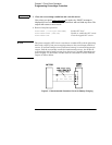
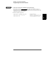
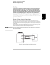
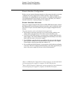
Remote Voltage Sensing Connections
Remote voltage sensing requires connecting the load leads from output
terminals to the load and connecting the sense leads from sense terminals to
the load as shown below. Observe polarity when connecting the sensing leads
to the load.
Notice that the metal shorting bars should be removed from the output and
sense terminals for remote voltage sensing connections.
Note
For local voltage sensing connections, the sense leads must be connected to
the output terminals.
Figure 3-2. Remote Voltage Sensing Connections