


Chapter 3 Front-Panel Operation
RS-232 Interface Configuration
63
3
Connection to a Computer or Terminal
To connect the power supply to a computer or terminal, you must have the
proper interface cable. Most computers and terminals are DTE (Data Terminal
Equipment) devices. Since the power supply is also a DTE device, you must
use a DTE-to-DTE interface cable. These cables are also called null-modem,
modem-eliminator, or crossover cables.
The interface cable must also have the proper connector on each end and the
internal wiring must be correct. Connectors typically have 9 pins (DB-9
connector) or 25 pins (DB-25 connector) with a “male” or “female” pin
configuration. A male connector has pins inside the connector shell and a
female connector has holes inside the connector shell.
If you cannot find the correct cable for your configuration, you may have to
use a wiring adapter. If you are using a DTE-to-DTE cable, make sure the
adapter is a “straight-through” type. Typical adapters include gender changers,
null-modem adapters, and DB-9 to DB-25 adapters.
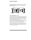
The cable and adapter diagrams shown below can be used to connect the
power supply to most computers or terminals. If your configuration is
different than those described, order the Agilent 34399A Adapter Kit. This kit
contains adapters for connection to other computers, terminals, and modems.
Instructions and pin diagrams are included with the adapter kit.
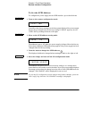
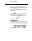
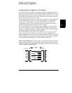
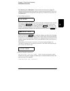
DB-9 Serial Connection If your computer or terminal has a 9-pin serial port
with a male connector, use the null-modem cable included with the Agilent
34398A Cable Kit. This cable has a 9-pin female connector on each end. The
cable pin diagram is shown below.
Instrument
PC
DB9
Male
DB9
Female
DB9
Female
DB9
Male
DCD
RX
TX
DTR
1
2
3
4
5
6
7
8
9
GND
DSR
RTS
CTS
RI
1
2
3
4
5
6
7
8
9
DCD
RX
TX
DTR
GND
DSR
RTS
CTS
RI
5182-4794
Cable