


Chapter 2 Initial Operation
Output Checkout
30
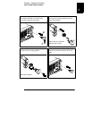
Current Output Checkout
The following steps check basic current functions with a short across the
power supply’s output.
1
Turn on the power supply.
The power supply will go into the power-on / reset state; the output is disabled
(the
OFF annunciator turns on); the 15V/7A range is selected (the 15V
annunciator turns on); and the knob is selected for voltage control.
2
Connect a short across (+) and (-) output terminals with an insulated
test lead.
3
Enable the output.
The
OFF annunciator turns off and the 15V, OVP, and OCP annunciators are lit.
The
CV or CC annunciator turns on depending on the resistance of the test
lead. The blinking digit can be adjusted by turning the knob. Notice that the
display is in the meter mode. ‘‘Meter mode’’ means that the display shows the
actual output voltage and current.
4
Adjust the voltage limit value to 1.0 volt.
Set the display to the limit mode (the
Limit annunciator will be blinking).
Adjust the voltage limit to 1.0 volt to assure CC operation. The
CC annunciator
will turn on.
5
Check that the front-panel ammeter properly responds to knob control
for the 15V/7A range.
Set the knob to the current control, and turn the knob clockwise or counter
clockwise when the display is in the meter mode (the
Limit annunciator is off).
Check that the ammeter responds to knob control and the voltmeter indicates
nearly zero (the voltmeter will show the voltage drop caused by the test lead).
Power
Output On/Off
Display Limit
Volt/Curr