


Chapter 2 Initial Operation
Output Checkout
29
2
Output Checkout
The following procedures check to ensure that the power supply develops its
rated outputs and properly responds to operation from the front panel. For
complete performance and verification tests, refer to the Service Guide.
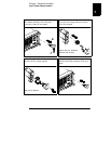
For each step, use the keys shown on the left margins.
Voltage Output Checkout
The following steps verify basic voltage functions with no load.
1 Turn on the power supply.
The power supply will go into the power-on / reset state; the output is disabled
(the
OFF annunciator turns on); the 15V/7A range is selected (the 15V
annunciator turns on); and the knob is selected for voltage control.
2 Enable the outputs.
The
OFF annunciator turns off and the 15V, OVP, OCP, and CV annunciators are
lit. The blinking digit can be adjusted by turning the knob. Notice that the
display is in the meter mode. ‘‘Meter mode’’ means that the display shows the
actual output voltage and current.
3
Check that the front-panel voltmeter properly responds to knob
control for the 15V/7A range.
Turn the knob clockwise or counter clockwise to check that the voltmeter
responds to knob control and the ammeter indicates nearly zero.
4
Ensure that the voltage can be adjusted from zero to the full rated
value.
1
Adjust the knob until the voltmeter indicates 0 volts and then adjust the knob
until the voltmeter indicates ‘‘
15.0 volts’’.
1
You can use the resolution selection keys to move the blinking digit to the
right or left when setting the voltage.
Power
Output On/Off