OmniSwitch 6600 Family Chassis and Hardware Components OmniSwitch 6600-P24
OmniSwitch 6600 Family Hardware Users Guide September 2006 page 2-9
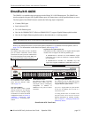
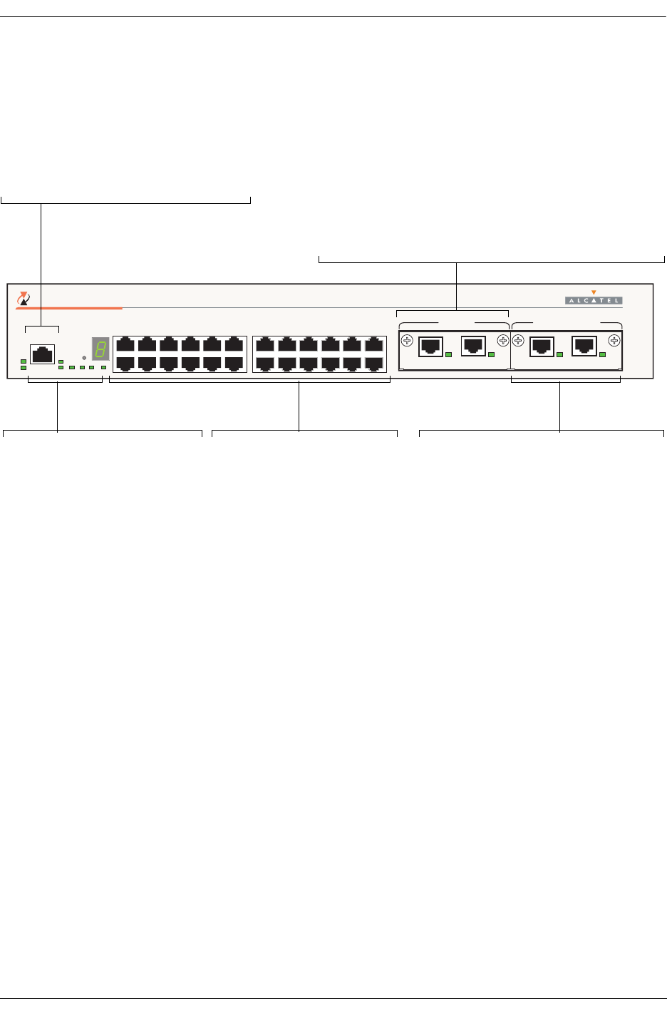
Refer to the illustration below for more front panel information. For detailed LED descriptions, refer to
page 2-18. For information on the chassis rear panel, refer to page 2-20.
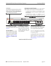
OmniSwitch 6600-P24 Front Panel
CONSOLE
3
4
5
6
7
8
9
10
11
12
13
14
15
16
17
18
19
20
21
22
23
24
1
2
EXPANSION/STACKINGEXPANSION
25 26 27 28
TM
OmniSwitch 6600-P24
OK1
OK2
PS1
PS2
PRI
SEC
TEMP
FAN
SEL
LINK/ACT
LINK/ACT
LINK/ACT
LINK/ACT
10/100 Ethernet Ports
The OS6600-P24 provides 24
Power over Ethernet (PoE) 10/100
Ethernet ports. These ports are
twisted-pair and are individually
configurable as 10BaseT or
100BaseTX. The ports use RJ-45
connectors. For information more
information, refer to page 2-18.
Console Port
The OS6600-P24 front panel provides one RJ-
45 port for console connections. Serial console
connections are used by network administrators
for switch management. This female RJ-45 con-
nector provides a DCE console connection.
Stacking or Uplink Module Slot
The OS6600-P24 provides an additional slot
that can accommodate either a stacking mod-
ule or a Gigabit Ethernet uplink module.
If you use a Gigabit Ethernet uplink module
in this slot, the OS6600-P24 must be used as
a stand-alone switch.
A stacking module must be installed in this
slot if the switch is to be used in a stack. For
detailed information on stacking switches,
refer to Chapter 4, “Managing OmniSwitch
6600 Family Stacks.”
Gigabit Ethernet Uplink Module Slot
The OS6600-P24 provides a dedicated slot for Gigabit Ethernet
uplink modules. This slot supports the following module types:
• OS6600-GNI-C2—Provides two fixed 1000BaseT copper
connections (uses two RJ-45 connectors). Supports distances
up to 100 meters.
• OS6600-GNI-U2—Provides two MiniGBIC bays that
support hot-swappable 1000BASE-X MiniGBIC transceivers.
Status and Slot Indicator LEDs
For information on the OS6600-P24’s
status and slot indicator LEDs, refer
to page 2-18.
Slot Selector Button
The slot selector button, located
directly beneath the slot indicator
LED, is used to manually assign
slot numbers to switches in stacked
configurations.


