


AT-29xx Series Gigabit Ethernet Network Adapters Installation Guide
29
Connecting the Network Cables
All the fiber Gigabit Ethernet network adapters have two fiber optic
connectors for attaching the system to a compatible link partner, or an
IEEE 802.3z compliant gigabit switch. After connecting the system to the
network and power is supplied, the adapter performs auto-negotiation and
attempts to establish the connection at 1000 Mbps full-duplex only.
To connect a network cable to the adapter, perform the following
procedure:
1. Prepare a fiber optic cable according to the specifications in Table 3.
Warning
The fiber optic ports contain a Class 1 laser device. When the ports
are disconnected, always cover them with the provided plug.
Exposed ports may cause skin or eye damage.
2. Connect one end of the cable to the adapter.
3. Connect the other end of the cable to the appropriate Ethernet network
port or fiber optic port.
Note
After the cable is properly connected at both ends, the adapter port
LEDs should be functional. See Table 1 on page 18 for a description
of adapter port LED operation. For driver installation and
configuration instructions, refer to the software configuration for a
specific driver.
The AT-2972T/2 has two copper connectors for attaching the system to a
compatible link partner. After you connect to the network and power is
supplied, the adapter performs auto-negotiation and attempts to establish
the connection at the appropriate speed and duplex mode.
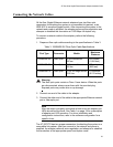
Table 3. 1000BASE-SX Fiber Optic Cable Specifications
Port Type Connector Media
Maximum
Distance
1000BASE-SX Fiber Optic 50 µm multimode
850 nm
550 meters
(1,804 feet)
1000BASE-SX Fiber Optic 62.5 µm multimode
850 nm
275 meters
(853 feet)
1000BASE-LX Fiber Optic 9.125 µm single mode
1310 nm
10 kilometer
(6.213 miles)