


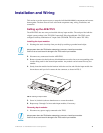

Installation and Wiring
18
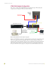
VTM-D15/A 15" MultiMedia Touch Panel Systems
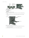
3. Thread the cables on the back of the panel either through the wall cutout (if the cables are
being routed through the wall).
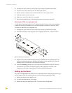
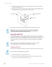
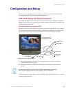
4. Supporting the monitor with both hands, slide the Monitor Bracket (arrow side up) into the
Surface Bracket holes and slide it down until it snaps into place.
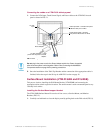
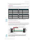
Wiring the AXB-TPI/3
The AXB-TPI/3 can either use a 4-pin AXlink connector for power and data or a 2-pin PWR
connector from a PSN6.5 to directly supply power. When trying to provide power through the 4-pin
AXlink, if the distance between the AXB-TPI/3 and the Central Controller exceeds the power
consumption limits, you must connect an optional 12 VDC power supply to the 2-pin PWR
connector.
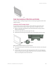
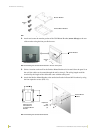
Preparing captive wires
You will need a wire stripper and flat-blade screwdriver to prepare and connect the captive wires.
1. Strip 0.25 inch (6.35 mm) of insulation off all wires.
2. Insert each wire into the appropriate opening on the connector, according to the wiring
diagrams and connector types described in this section.
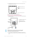
FIG. 17 Attaching the panel (with Monitor Bracket) to the Surface Mount Bracket (on surface/wall)
Monitor Bracket
Surface Mount Bracket
Monitor Bracket
Do not plug in the power cord to the Power Adapter at this time. Power is supplied
after the entire system is wired together. Refer to the Connecting the MultiMedia
Components section on page 20 for powering procedures.
Do not connect power to the TPI/3 until wiring is complete. If you are using a 12 VDC
power supply, apply power to the TPI/3 only after installation is complete.
Never pre-tin wires for compression-type connections.