Installation and Wiring
21
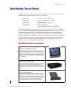
VTM-D15/A 15" MultiMedia Touch Panel Systems
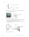
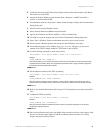
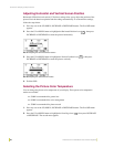
4. Connect a standard RS-232 cable to the Program Port on the front of the TPI/3 Touch Panel
Interface to the COM1 or COM2 ports on the back of your computer.
5. Verify that the VTM-D15/A display is switched Off.
6. Provide power by either connecting the 4-pin AXlink cable from the Central Controller to the
AXlink connector port at the rear of the TPI/3 or by using a local PSN6.5 power supply. Use
the local PSN only if the distance from the power source exceeds the wiring lengths for the
TPI/3 as described in the Wiring guidelines section on page 19. The AXB-TPI/3 beeps when
you apply power and again when AXlink communication is detected.
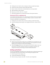
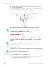
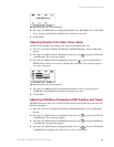
7. Connect the Power Adapter to the female connector on the Power Cord and then connect the
Power Cord to an electrical outlet (FIG. 20).
Your system is now connected and receiving power.
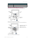
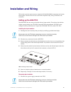
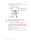
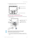
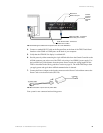
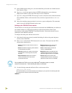
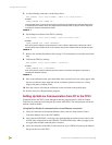
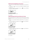
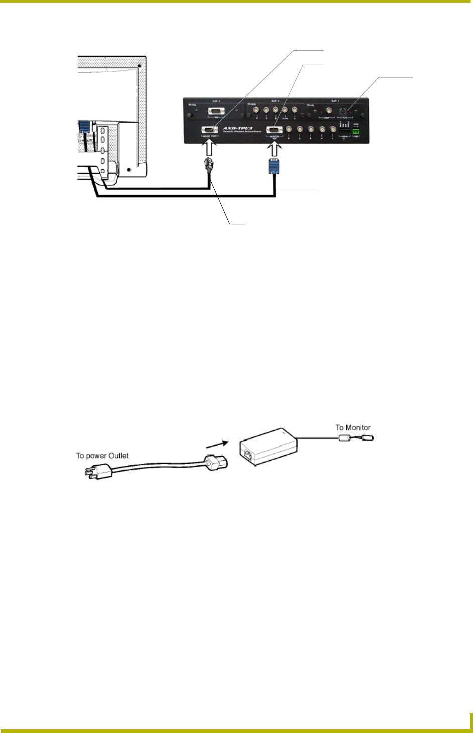
FIG. 19 Attaching the cables from the panel to the rear of the AXB-TPI/3
FIG. 20 Connection of power cord to power cable
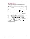
VGA Input cable - connects to
Monitor Out port on TPI/3
Touch Screen cable - connects to
Mouse Port on TPI/3
Mouse Port
Monitor Out port
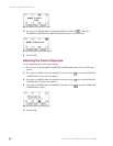
Connect
incoming
video to
TP3-VID
card