


Installation and Wiring
20
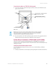
VTM-D15/A 15" MultiMedia Touch Panel Systems
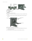
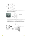
1. Unscrew the PWR and GND wires on the terminal end of the PSN6.5 2-pin cable.
2. Pair the GND wires from the PSN6.5 and the Central Controller AXlink connectors together
and insert them into the clamp position for GND on the TPI/3’s AXlink connector.
3. Tighten the clamp to secure the two GND wires.
4. Place the PWR wire from the PSN6.5 into the open clamp position for PWR on the TPI/3’s
AXlink connector.
5. Tighten the clamp to secure the PWR wire.
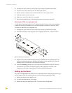
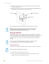
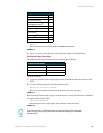
Using the VGA IN DB-15 (male) high-density connector
Connect the VTM-D15/A’s DB-15 (female) video connector to the VGA IN DB-15 (male)
high-density connector on the rear panel of the touch panel. The following table below lists the
VGA IN DB-15 connector pinouts.
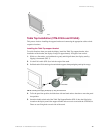
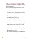
Connecting the MultiMedia Components
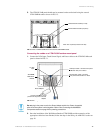
1. Connect the VGA signal cable from the rear of the VTM-D15/A panel to the Monitor Out port
on the back of the TPI/3 (FIG. 19).
2. Connect the Touch Screen signal cable from the rear of the panel to the Mouse Port on the back
of the TPI/3.
3. Connect the incoming video signal connector to either the Composite or S-Video connector
ports on the TP3-VID card. Refer to the Setting up the AXB-TPI/3 section on page 11 for input
card installation instructions.
Do not provide power to the TPI/3 at this time. Power is supplied after the entire
system is wired together. Refer to the following section for powering procedures.
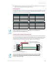
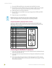
VGA IN DB-15 Connector Pinouts
Pin Signal Function
1 Red Red signals
2 Green Green signals
3 Blue Blue signals
4 N/A Not used
5 GND Signal Ground
6 RAGND Red analog ground
7 GAGND Green analog ground
8 BAGND Blue analog ground
9 N/A Not used
10 SAGND Synchronization analog ground
11 N/A Not used
12 N/A Not used
13 HSYNC Horizontal synchronization signal
14 VSYNC Vertical synchronization signal
15 N/A Not used
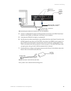
VGA DB-15 (male)
connector
10
6
5
1
15
11