21
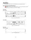
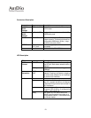
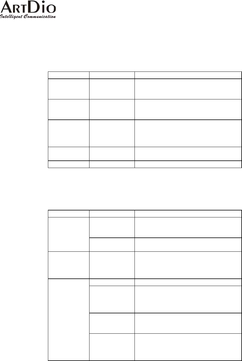
Connectors Description
Connectors Type Description
To WAN
10/100
Ethernet
RJ45 with MDI-X onnect to the Ethernet port Designed to c
on the router.
To LAN
10/100
Ethernet
RJ45 with MDI nnect to one of the LAN’s Designed to co
HUB/Switch ports.
EIA-232
DB-9 DTE a VT100 terminal or Can be connected to
system console. The terminal should be
configured to 9600 baud, 8 bits, 1 stop
bits and none parity check.
POTS Ports
IDC Jack or
RJ-11 jack
Where analog telephone lines are
connected
Power
AC 90-120 Volt, 220~250Volt
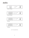
ED Description
LED Label Description
L
LNK/ACT ates a network connection. When lit, indic
The LED will flash when network traffic is
detected.
10/100
t
100Mbps
Etherne
Indicating the network is running at
100Mbps
Port
ation
oing
Inform
LOOP/
RING
When lit, indicates a loop has been
detected. Flashing indicates an outg
call on the FXS interface or an incoming
call on the FXO interface.
Power Indicates stable power.
Alarm The device will halt and the indicator will
stay lit if a system test failure is detected,
or if there are loop current lost counted on
FXO interfaces.
Master If this device is configured as the master,
this green LED will be on. If configured as
a slave , it will remain off .
Device
Ready
if
This green LED will be on when this
device is configured as the master or
configured as a slave , is connected with
the remote master.


