


Management
Page 3-4
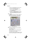
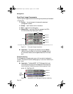
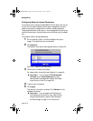
Front Panel Image Components
The front panel image contains the following components (as illustrated
in Figure 3-4):
❏ Device — the entire stack of hubs and the attached
management module.
❏ Group — each module within the device.
❏ Port — each port on each group.
❏ Status LEDs — real-time LEDs that represent the LEDs
on the modules; they display port activity.
Figure 3-4 Front panel image components
▲ Important: Throughout this manual, the term device
refers to the entire stack of hubs; the term group refers to
an individual module; the term port refers to an individual
port.
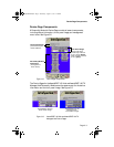
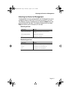
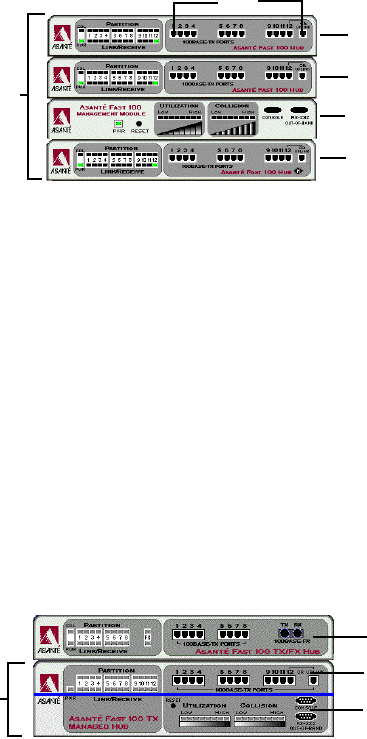
Group Numbering
For management purposes, each group within a device is assigned a
number. The bottom module is always group 15, the next module up is
group 14, etc.
▲ Important: The AsantéFAST 100 TX Managed Hub mod-
ule contains two groups (the management module and the
hub); therefore, it uses two group numbers (group 15 and
group 14). See Figure 3-5.
Figure 3-5 AsantéFAST 100 TX Managed Hub group numbering
Group 15*
Group 14
Group 13
Group 12
*The bottom module is assigned Group 15, the next module up is assigned Group 14, etc.
Device
Ports
Group 14
Group 13
Group 15
100TX
Managed
Hub
100NMM PM book Page 4 Wednesday, August 27, 1997 12:40 PM