Accessing the Device
Page 3-4
Front Panel Image
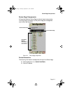
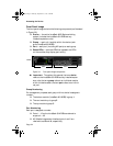
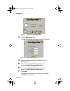
The front panel image contains the following components (as illustrated
in Figure 3-3):
❏ Device — the entire IntraStack 6000 Series switching
system (includes the IntraStack 6014DSB and any
installed expansion units).
❏ Group — each unit (module) within the device (such
as the IntraStack 6014DSB).
❏ Port — each port (including MII ports) on each group.
❏ Status LEDs — real-time LEDs that represent the LEDs
on the modules; they display port activity.
Figure 3-3 Front panel image components
▲ Important: Throughout this manual, the term device
refers to the IntraStack 6014DSB and any installed expan-
sion units; the term group refers to an individual module
within the device stack; the term port refers to an individ-
ual port.
Group Numbering
For management purposes, each group within a device is assigned a
number:
❏ The bottom module (IntraStack 6014DSB) is group 1
❏ The next module up is group 2
❏ The top module is group 3
Port Numbering
Each port is assigned a number.
❏ Ports 1 – 12 on the IntraStack 6014DSB are referred to
as ports 1 – 12.
❏ MII (Media Independent Interface) ports I and II are
referred to as 13 and 14, respectively.
Device
Ports
LEDs
Book Page 4 Thursday, September 18, 1997 4:28 PM


