


ASUS NCCH-DRASUS NCCH-DR
ASUS NCCH-DRASUS NCCH-DR
ASUS NCCH-DR
2-112-11
2-112-11
2-11
2.2.52.2.5
2.2.52.2.5
2.2.5
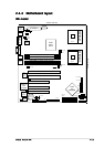
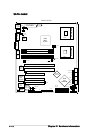
Layout contentsLayout contents
Layout contentsLayout contents
Layout contents
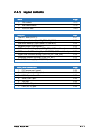
SlotsSlots
SlotsSlots
Slots
PagePage
PagePage
Page
1. CPU sockets 2-13
2. DDR DIMM sockets 2-16
3. PCI/PCI-X slots 2-20
JumpersJumpers
JumpersJumpers
Jumpers
PagePage
PagePage
Page
Clear RTC RAM (CLRTC1) 2-21
CPU fan pin selection (3-pin FM_CPU1, FM_CPU2) 2-22
USB device wake-up (3-pin USBPW12, USBPW34) 2-22
Keyboard power (3-pin KBPWR1) 2-23
SATA controller setting (3-pin SATA_EN1)
SATA models only
2-23
SATA controller LED setting (3-pin 8130LED1)
SATA models only
2-24
Gigabit LAN controller setting (3-pin LAN_EN1; LAN_EN2) 2-24
Integrated graphics controller (3-pin VGA_EN1) 2-25
Force BIOS recovery (3-pin RECOVERY) 2-25
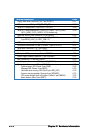
Rear panel connectorsRear panel connectors
Rear panel connectorsRear panel connectors
Rear panel connectors
PagePage
PagePage
Page
1. PS/2 mouse port (green) 2-26
2. PS/2 keyboard port (purple) 2-26
3. USB 2.0 ports 1 and 2 2-26
4. Serial (COM1) port 2-26
5. VGA port 2-26
6. LAN1 (RJ-45) port 2-26
7. LAN2 (RJ-45) port 2-26