


2-122-12
2-122-12
2-12
Chapter 2: Hardware informationChapter 2: Hardware information
Chapter 2: Hardware informationChapter 2: Hardware information
Chapter 2: Hardware information
Internal connectorsInternal connectors
Internal connectorsInternal connectors
Internal connectors
PagePage
PagePage
Page
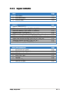
Floppy disk drive connector (34-1 pin FLOPPY) 2-27
IDE connectors (40-1 pin PRI_IDE, SEC_IDE) 2-27
Serial ATA connectors (7-pin SATA1, SATA2) 2-28
Serial ATA RAID connectors (7-pin SATA_RAID1, SATA_RAID2, 2-29
SATA_RAID3, SATA_RAID4)
SATA models only
Hard disk activity LED connector (2-pin HDLED) 2-29
CPU and system fan connectors (4-pin CPU_FAN1/2, 2-30
3-pin REAR_FAN1/2, FRNT_FAN1/2)
USB port connector (10-1 pin USB34) 2-30
SSI power connectors (24-pin ATXPWR1, 8-pin ATX12V1) 2-31
Serial port connector (10-1 pin COM2) 2-32
Printer port connector (26-1 pin LPT1) 2-32
Backplane SMBus connector (6-1 pin BPSMB1) 2-33
Power supply SMBus connector (5-pin PSUSMB1) 2-33
BMC connector (16-pin BMCCONN1) 2-34
Auxiliary panel connector (20-2 pin AUX_PANEL1) 2-34
System panel connector (20-pin PANEL1) 2-35
System power LED (Green 3-pin PLED) 2-35
Message LED (Brown 2-pin MLED) 2-35
Hard disk drive activity LED (Red 2-pin HDD_LED) 2-35
System warning speaker (Orange 4-pin SPEAKER) 2-35
ATX power button/soft-off button (Yellow 2-pin PWRSW) 2-35
Reset button (Blue 2-pin RESET) 2-35