


1-6
Chapter 1: Product introduction
1.4 Motherboard overview
Before you install the PU-DLS/PU-DL motherboard, familiarize yourself
with its physical configuration and available features to facilitate the
motherboard installation and future upgrades. A sufficient knowledge of the
motherboard specifications will also help you avoid mistakes that may
damage the board and its components.
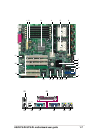
1.4.1 Major components
The following are the major components of the PU-DLS/PU-DL
motherboard as pointed out in the picture on page 1-7.
1. SSI-type power connector
2. DDR DIMM sockets
3. Intel
®
E7501 northbridge
4. Intel
®
P64H2 PCI-X Hub
5. 604-pin CPU sockets
6. 8-pin 12V SSI power connector
7. SCSI connector (optional)
8. Adaptec 7902W SCSI controller
9. Firmware hub (FWH)
10. IDE connectors
11. Standby power LED
12. SCSI connector
13. ASUS ASIC
14. CPU Power Fail LED
15. LPC Super I/O controller
16. Floppy connector
17. Intel
®
ICH3-S I/O Hub
18. ATI Rage-XL VGA controller
19. PCI-X slots (PCI-X1 to PCI-X4)
PCI slots (PCI1, PCI2)
20. Intel
®
82540EM 32-bit PCI
Gigabit Ethernet controller
21. Intel
®
82544GC 64-bit PCI-X
Gigabit Ethernet controller
22. PS/2 mouse port
23. Parallel port
24. RJ-45 port (for 32-bit LAN)
25. RJ-45 port (for 64-bit LAN)
26. VGA port
27. Serial port (COM1)
28. USB 1.1 ports 1 and 2
29. Keyboard port
The Adaptec 7902W SCSI controller and the onboard SCSI connectors
are available only on PU-DLS models.
See page 1-8 for the specifications of each component. Refer to
Chapter 2 for detailed information on the components.