


ASUS PU-DLS/PU-DL motherboard user guide
2-25
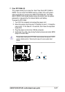
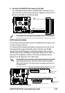
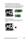
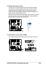
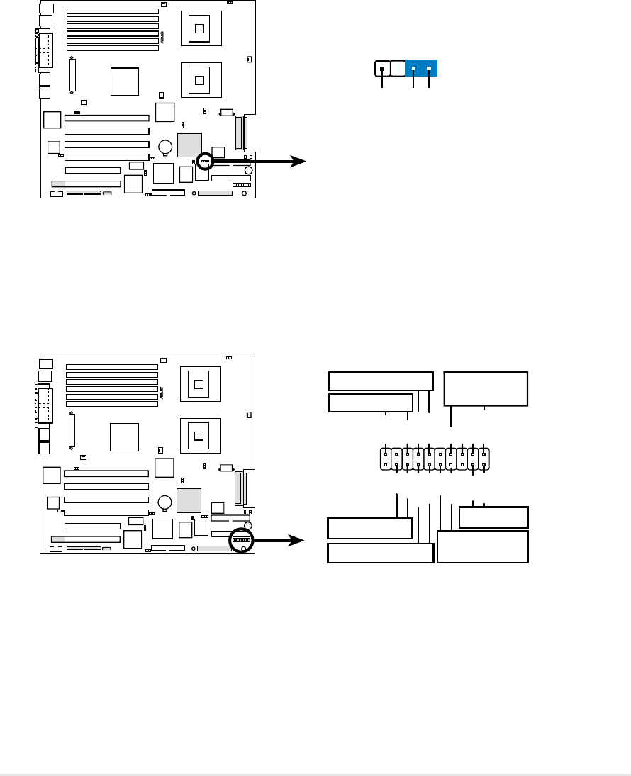
12. Chassis alarm lead (4-1 pin J6)
This lead is for a chassis designed with intrusion detection feature.
This requires an external detection mechanism such as a chassis
intrusion sensor or microswitch. When you remove any chassis
component, the sensor triggers and sends a high-level signal to this
lead to record a chassis intrusion event.
By default, the pins labeled “Chassis Signal” and “Ground” are shorted
with a jumper cap. If you wish to use the chassis intrusion detection
feature, remove the jumper cap from the pins.
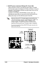
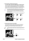
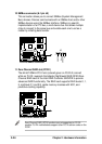
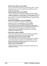
13. System panel connector (20-pin PANEL)
This connector accommodates several system front panel functions.
PU-DLS
®
PU-DLS Chassis Open Alarm Lead
J6
+5Volt
(Power Supply Stand By)
Chassis Signal
Ground
PU-DLS
®
*
Requires an ATX power supply.
PLED
Ground
MLED
PWR
+5VSB
+5V
Speaker
Speaker
Connector
Power LED
Ground
+5 V
Reset SW
SMI Lead
Message LED
ExtSMI#
Ground
Reset
Ground
Ground
ATX Power
Switch*
Keylock
Ground
Keyboard Lock
PU-DLS System Panel Connectors