


ASUS PU-DLS/PU-DL motherboard user guide
2-13
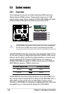
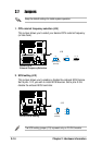
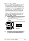
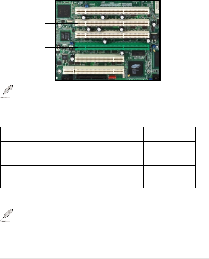
2.6.3 PCI slots
This motherboard implements the PCI-X (Peripheral Component Interconnect
Extended) bus technology to support up to 133MHz data transfers, or about
1.06GB/s. This bus technology is primarily designed for servers to increase
the performance of high bandwidth devices such as Ultra320 SCSI. PCI-X is
backward compatible with the earlier PCI bus technology making it possible to
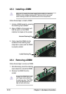
install PCI and PCI-X cards at the same time, but the bus speed will be that of
the slowest card. The following figure shows the four PCI-X slots and two PCI
slots on the motherboard.
PCI-X4
PCI-X3
PCI-X2
PCI-X1
PCI2
PCI1
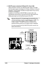
PCI-X slots (PCI X1 to X4)
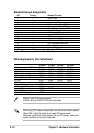
The PCI-X bus speeds vary depending on the number of expansion cards
installed on the slots.
* PCI-X1 slot on PU-DLS models supports a ZCR (Zero Channel RAID) card.
ZCR functions are not supported on PU-DL models. See section “2.8
Connectors” for more information on this slot.
PCI1/PCI2 slots
PCI1 and PCI2 are 32-bit/33MHz 5V PCI slots. PCI1 has a Low Pin Count
(LPC) signal connector to accommodate the ASUS Server Management
Card. The PCI bus speed for these slots is fixed at 33MHz.
PCI Bus Onboard device Card installed PCI-X bus speed
Channel A Intel 82544GC PCI-X LAN None 133 MHz
One
(on PCI-X3 or PCI-X4) 100 MHz
Two (on PCI-X3 and PCI-X4) 66 MHz
Channel B Adaptec AIC-7902W None 133 MHz
PCI-X Ultra-320 SCSI One (on PCI-X1 or PCI-X2) 100 MHz
Two (on PCI-X1 and PCI-X2) 66 MHz
PCI Bus Channel B as illustrated above applies only on PU-DLS models.
The PCI-X1 slot on PU-DL models is colored white.