18
ASUS TR-DLS User’s Manual
3. HARDWARE SETUP
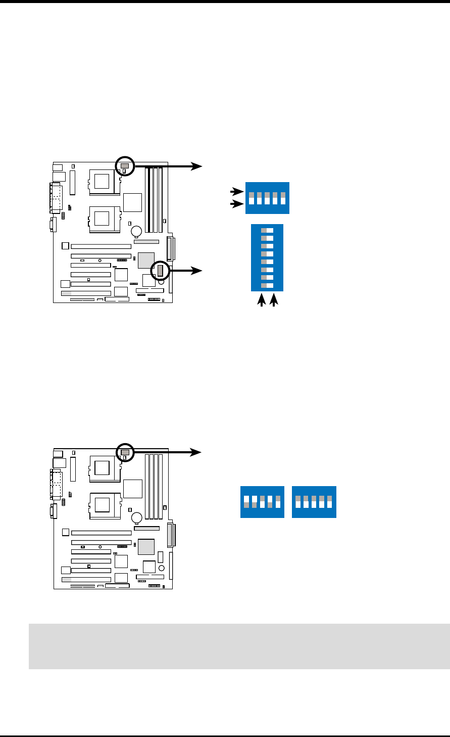
You may change the CPU core bus frequency multiple using the DIP switches. The
white block on a DIP switch represents the ON or OFF position. The figure below
shows the location of the DIP switches on the motherboard and the function of each
switch.
CAUTION! Set the CPU frequency only to the recommended settings. Frequencies
other than the recommended CPU bus frequencies are not guaranteed to be stable.
3.4 Motherboard Settings
3.4.1 Switches
1. CPU Frequency Selection (CLKSW)
This option tells the clock generator what frequency to send to the CPU. This
allows the selection of the CPU external frequency (or bus clock). The bus clock
multiplied by the the frequency multiple equals the CPU internal frequency (the
advertised CPU speed).
TR-DLS
TR-DLS CPU External Frequency Selection
CPU
100MHz
ON
12345
133MHz
ON
12345
CLKSW
TR-DLS
TR-DLS DIP Switches
CONFIG
1. Reserved
2. External Buzzer Setting
3. Reserved
4. Reserved
5. Frequency Multiple
6. Frequency Multiple
7. Frequency Multiple
8. Frequency Multiple
1. Frequency Selection
2. Frequency Selection
3. Frequency Selection
4. Frequency Selection
5. Frequency Selection
OFF
ON
ON
12345
CLKSW
ON
12345678
OFF
ON


