


32
3. HARDWARE SETUP
ASUS TR-DLS User’s Manual
3. H/W SETUP
Connectors
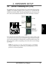
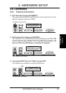
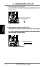
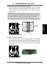
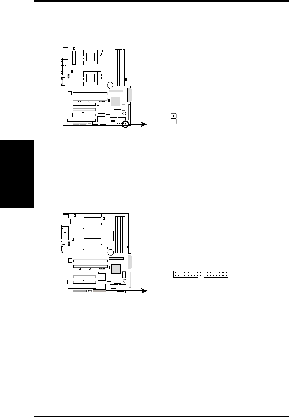
2) IDE/SCSI Activity LED (2-pin HDLED)
This connector supplies power to the chassis activity LED. Read and write activity
by devices connected to the primary/secondary IDE and SCSI connectors cause
the LED to light up.
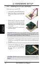
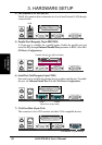
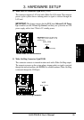
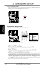
3) Floppy Disk Drive Connector (34-1 pin FLOPPY)
This connector supports the provided floppy drive ribbon cable. After connecting
the single end to the board, connect the two plugs on the other end to the floppy
drives. (Pin 5 is removed to prevent inserting in the wrong orientation when
using ribbon cables with pin 5 plugged).
TR-DLS
TR-DLS HD Activity LED
HD_LED
TIP: If the case-mounted LED does not
light, try reversing the 2-pin plug.
+
-
TR-DLS
NOTE: Orient the red markings on
the floppy ribbon cable to PIN 1.
TR-DLS Floppy Disk Drive Connector
PIN 1