


37
3. HARDWARE SETUP
ASUS TR-DLS User’s Manual
3. H/W SETUP
Connectors
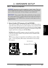
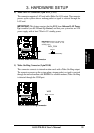
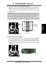
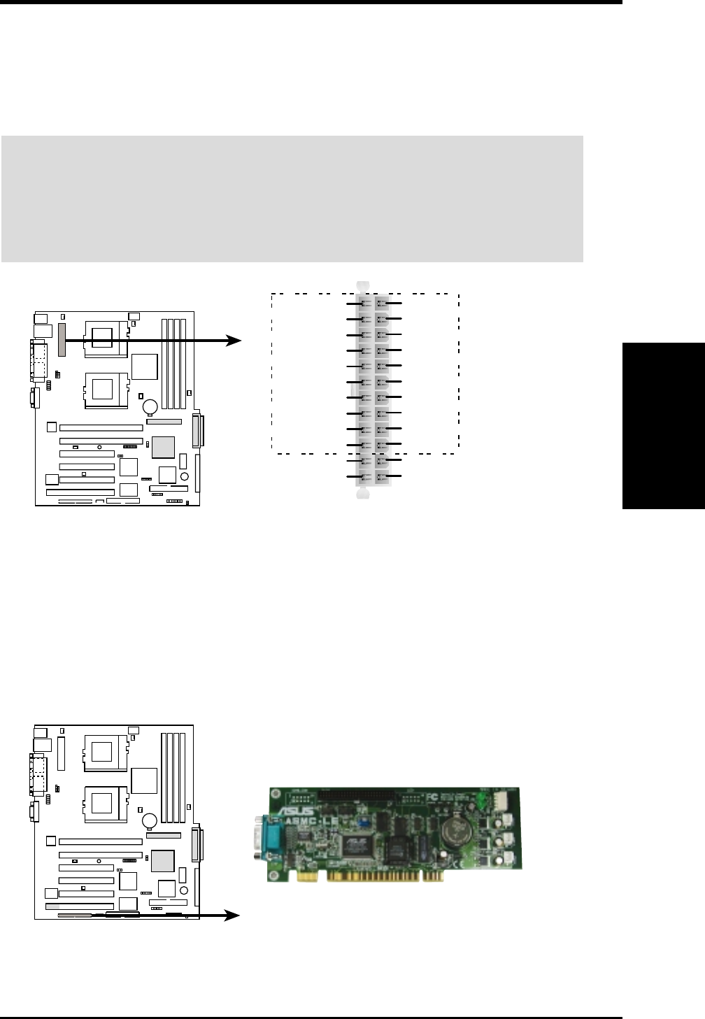
12) ASMC Connector (50-pin eRMC )
This connector allows you to connect the optional ASMC-LE or ASMC-ME
card using an ASMC interface cable. Install the ASMC card into the PCI6 slot
and connect the cable from the card to this connector. The PCI6 slot on the
motherboard has a Low Pin Count (LPC) signal connector to accommodate the
ASMC card.
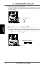
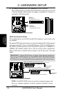
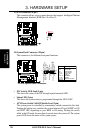
11) ATX Power Connector (20/24-pin block ATXPWR)
This connector is for an ATX power supply with 20/24-pin power connector. The
connector from the power supply is designed to fit this connector in only one
orientation. Find the proper orientation and push down firmly until the plug
completely fits in.
TR-DLS
TR-DLS ASMC Connector
TR-DLS
TR-DLS ATX Power Connector
+3 Volts
+3 Volts
Ground
+5 Volts
+5 Volts
Ground
Ground
Power OK
+5V Standby
+12 Volts
-5 Volts
+5 Volts
+3 Volts
-12 Volts
Ground
Ground
Ground
PSON#
Ground
+5 Volts
+12 Volts
+3 Volts
+5 Volts
1
Ground
For Power Supply
with 20-pin
Power Connector
24-pin Power Connector
IMPORTANT: Make sure that your ATX power supply can supply at least 720mA
on the +5-volt standby lead (+5VSB). The system may become unstable and
may experience difficulty powering up if the power supply is inadequate.
It is recommended that you purchase a power supply with 24-pin power connector.