


39
3. HARDWARE SETUP
ASUS TR-DLS User’s Manual
3. H/W SETUP
Connectors
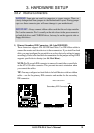
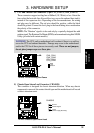
• Reset Switch Lead (2-pin)
This 2-pin connector connects to the case-mounted reset switch for rebooting
your computer without having to turn off your power switch. This is a preferred
method of rebooting to prolong the life of the system power supply.
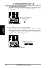
• System Power LED Lead (3-1 pin)
This 3-1 pin connector connects to the system power LED that lights up when
the system is powered on and blinks when it is in sleep or soft-off mode. This
feature can be programmed through the ASUS ASIC.
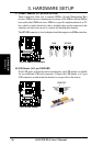
• NMI Lead (2-pin)
This 2-pin connector connects to a panel button to allow a non-mask interrupt
command to be sent to the operating system.
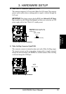
• System Warning Speaker Lead (4-pin)
This 4-pin connector connects to the case-mounted speaker.
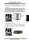
• HDD Activity LED (2-pin)
This connector supplies power to the IDE and SCSI activity LED. Read and
write activity by devices connected to the IDE and SCSI connectors cause this
LED to light up.