


38
3. HARDWARE SETUP
ASUS TR-DLS User’s Manual
3. H/W SETUP
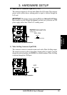
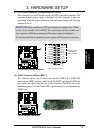
Connectors
• NIC Activity LED Lead (2-pin)
This shows the status of the NIC through a panel-mounted LED.
• Status LED (2-pin)
This shows the system status as programmed through the ASUS ASIC.
• ATX Power Switch / Soft-Off Switch Lead (2-pin)
The system power is controlled by a momentary switch connected to this lead.
Pushing the button once switches the system between ON and SLEEP or ON
and SOFT OFF, depending on your BIOS or OS setting. Pushing the switch
while in the ON mode for more than 4 seconds turns the system off. The system
power LED shows the status of the system power.
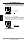
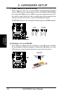
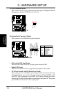
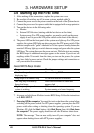
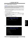
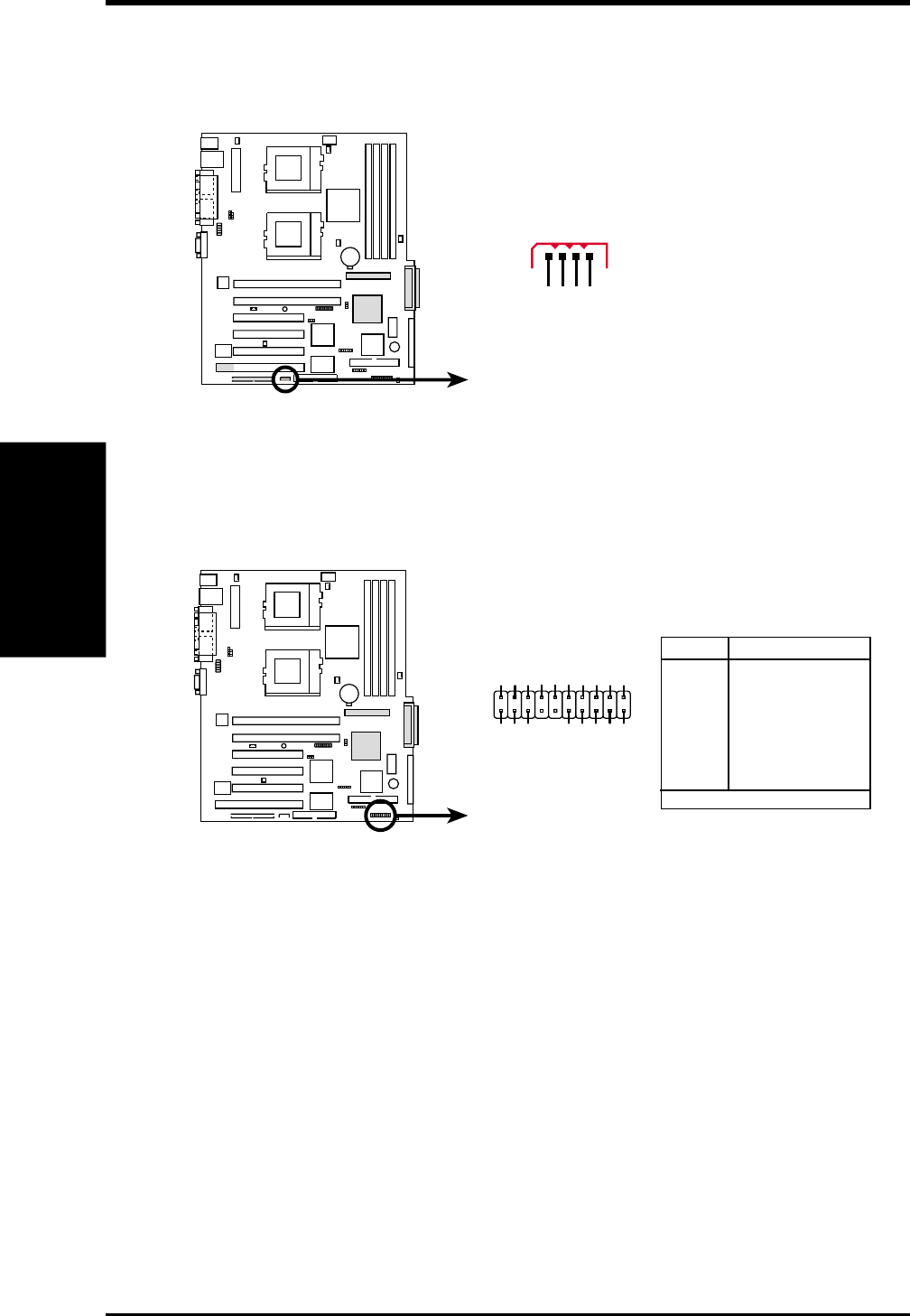
14) System Panel Connector (20-pin )
This connector is for different front panel functions.
TR-DLS
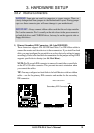
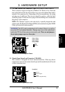
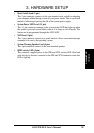
TR-DLS IPMI Connector
IPMIDATA
GND
IPMICLK
NC
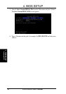
13) IPMI Connector (4-pin )
This connector allows you to connect devices that support Intelligent Platform
Manangement Interface (IPMI) Rev1.0 or Rev1.5.
TR-DLS
TR-DLS System Panel Connectors
GND
NIC activity LED+
Power LED +
HDD access LED–
Status LED –
Status LED+
RESET button
GND
+5V
HDD access LED+
Power LED –
GND
Speaker
NIC activity LED–
Power Switch
110
11 20
NMI button
Keylock
Pin Connector
1 & 12 NIC Activity LED
2 & 3 Status LED
6 & 7 Power Switch
9 & 10 Reset Switch
11 & 13 Power LED
14 Keylock
15* & 16 NMI Button
17 & 20 Speaker
18 & 19 HDD Access LED
* Shared