


8
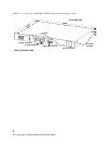
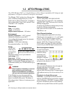
Installation: ATTO iPBridge 2700E
Embedded in the Ethernet management port
connector:
a lighted green LED shows a valid
link; off indicates that no link is present. A
separate blinking yellow LED indicates activity.
A bicolor Ready/Fault LED
lights green to
indicate ready, lights yellow to show a faulted
condition, and is off to indicate not ready.
Installation instructions
1 Install the iPBridge 2700C in the target device.
(See the board layout diagram below.)
2 Connect Fibre Channel devices to the iPBridge
and attach CAT 6 or CAT 5E cables to the GbE
port(s) on the iPBridge. (For details, refer to
Cabling
on page iii of the Appendix).
3 Configure the iPBridge using the instructions in
Configuring the iPBridge
on page 9.
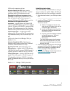
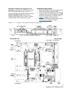
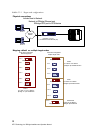
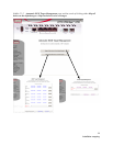
Exhibit 1.2-1 iPBridge 2700 faceplate and board configuration
Fibre Channel ports
10/100
Ethernet port
GbE ports
LEDs
FC Link FC Activity GbE Speed
GbE Activity
Ready/Fault
Reset
button
ActivityLink
serial header
Fibre
Channel
ports
cPCI
power
10/100
Ethernet
port
GbE
ports
mounting hole
mounting hole
mounting hole
6-pin
power
reset
switch
Faceplate side Power side