


26
Troubleshooting
• a bicolor LED, embedded in the connector on
each Gigabit Ethernet port, indicates 100/1000
MbE speed. Green on indicates 100MbE and
yellow on indicates 1000 MbE.
• a green LED for each Gigabit Ethernet port
indicates link/activity, where on solid indicates
link, blinking indicates activity and off is no link is
present.
• a green LED for each Fibre Channel port
indicates link where off means no link.
• A separate lighted green LED for each Fibre
Channel port shows activity and an unlit LED
means no activity.
Inspect the front side LEDs (iPBridge 2700R/D only)
(see Exhibit 5.0-2):
• a green power LED; on means power is on; off
means power is off.
• a yellow LED on each Ethernet port indicates
100/1000 MbE speed, where off means 100
MbE and on means 1000 MbE.
• a green LED on each Ethernet port activity,
where off means no activity and on means
activity.
• a bicolor LED on each Fibre Channel port
indicates FC speed. Off is 1G FC, green is 2G
FC and yellow indicates 4G FC.
• a green LED on each Fibre Channel port
indicates activity, where off means no activity
and on means activity.
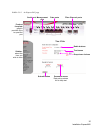
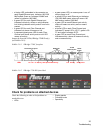
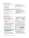
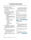
Exhibit 5.0-1 iPBridge 2700C faceplate
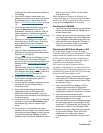
Exhibit 5.0-2 iPBridge 2700 R/D front label
Check for problems on attached devices
Check the following in order to find problems on
attached devices:
• LEDs
• Display panels
• Firmware levels
• Operability
Fibre Channel ports
10/100
Ethernet port
GbE ports
LEDs
FC Link FC Activity GbE Speed
GbE Activity
Ready/Fault
Reset
button
ActivityLink