


Operators Manual
ALS 330/430
Release 4/06 Page 60 Connections and signals
8.3 Input signals
This machine (dispenser) is provided with photo coupled inputs for:
y
the product sensor signal
y
an inhibit signal for inhibiting labelling
y
a signal from an OD control which shows the end of the material roll.
y
a signal from an automatic product speed follower
y
the EP applicator signals from the HOME and END switches
y
an unused input for future extensions or customer specific software (used for loop control in
the 720)
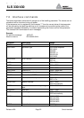
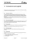
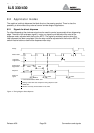
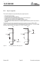
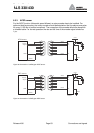
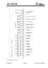
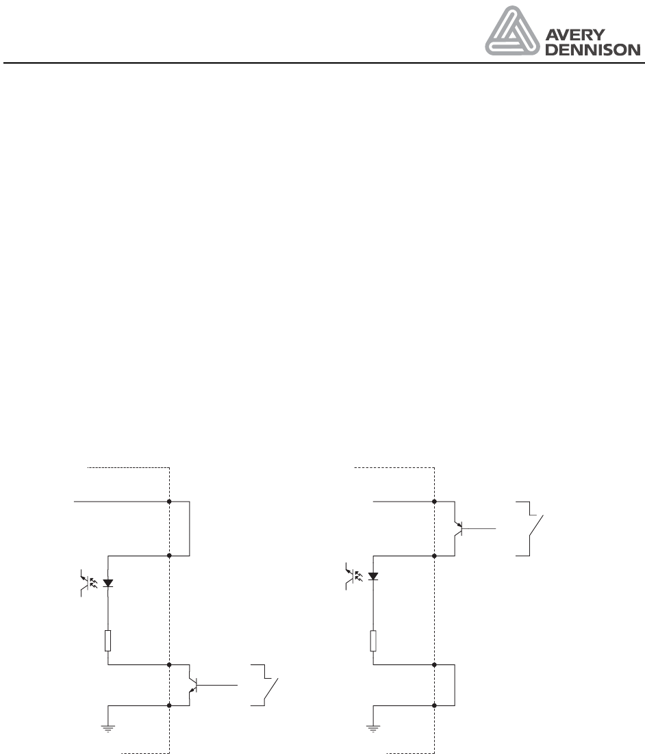
The inputs are galvanically separated through photo couplers to connect to PNP or NPN
outputs. The wiring and the connection of the signal plug is shown otherwise. The input voltage
across the inputs must be in the range of 15 V to 30 V to switch active.
ln+
Signal
ln-
Machine
(alternative switch)
+24V DC
NPN
Opto-
isolator
2K2
ln+
Signal
ln-
Machine
(alternative switch)
+24V DC
PNP
Opto-
isolator
2K2
Figure 21: Connecting NPN (left) or PNP (right) inputs.