


724-746-5500 | blackbox.com
Page 11
Chapter 2: Overview
2.4 Hardware Description
2.4.1 18-Port Gigabit Smart Switch Eco Fanless (LGB2118A)
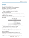
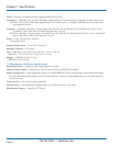
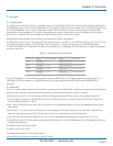
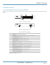
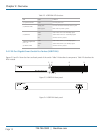
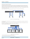
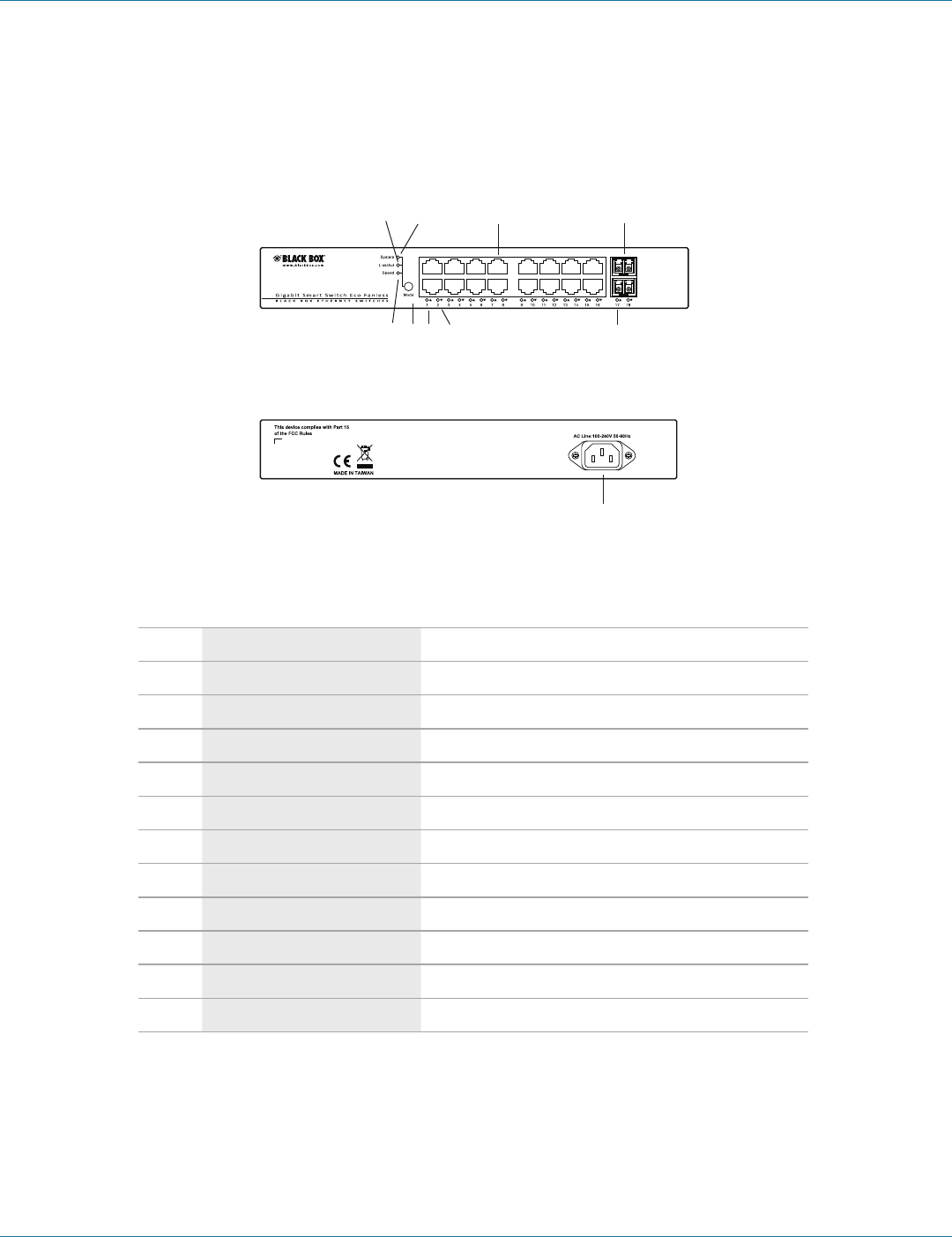
Figures 2-1 ad 2-2 show the front and back panels of the switch. Table 2-2 describes its components. Table 2-3 describes the LEDs
in detail.
7 1 2 3 4
5 6 8 9
Figure 2-1. LGB2118A front panel.
10
Figure 2-2. LGB2118A back panel.
Table 2-2. LGB2118A components.
Number Component Description
1 (1) Mode button Switches between what is being displayed by LEDs.
2 (16) TP port status LEDs For details, see Table 2-3.
3 (16) TP port speed LEDs For details, see Table 2-3.
4 (2) SFP port status LEDs For details, see Table 2-3.
5 Link/Act LED Lit to show switch is in Link/Act mode.
6 System LED Lit to show switch is in System mode.
7 Speed LED Lit to show switch is in Speed mode.
8 (16) 10/100/1000BASE-T RJ-45 ports 10-/100-/1000-Mbps Ethernet ports
9 (2) 100/1G SFP ports Connect up to two SFP links.
10 (1) AC power socket (on back of unit) IEC-320 power connection.
11 (1) Power LED* (on left side of unit) Lights when power is on.
*Not shown in Figure 2-1 or 2-2.