


724-746-5500 | blackbox.com
Page 13
Chapter 2: Overview
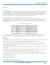
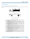
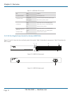
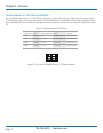
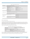
Table 2-4. LGB2124A components.
Number Component Description
1 (1) Mode button Switches between what is being displayed by LEDs.
2 (24) TP port status LEDs For details, see Table 2-5.
3 (24) TP port speed LEDs For details, see Table 2-5.
4 (4) SFP port status LEDs For details, see Table 2-5.
5 Link/Act LED Lit to show switch is in Link/Act mode.
6 System LED Lit to show switch is in System mode.
7 Speed LED Lit to show switch is in Speed mode.
8 (24) 10/100/1000BASE-T RJ-45 ports 10-/100-/1000-Mbps Ethernet ports
9 (4) 100/1G SFP ports Connect up to two SFP links.
10 (1) AC power socket (on back of unit) IEC-320 power connection.
11 (1) Power LED* (on left side of unit) Lights when power is on.
*Not shown in Figure 2-3 or 2-4.
Table 2-5. LGB2124A LED functions.
LED Color Function
(1) System Power LED Green Lit when +3.3 V power is on.
(20) LINK/ACT LEDs
Steady green
Blinking green
Lit when connection with remote device is good.
Blinks when any traffic is present.
(20) SPD LEDs
Green
Yellow
Off
Green when TP link is on 1000 Mbps speed
Yellow when T link is on 10/100 Mbps speed.
Off when no link is present.
1000SX/LX Gigabit fiber
port 21, 22, 23, 24
(2) LINK/ACT LEDs
Green
Yellow
Off
Green when SFP link is on 1000 Mbps speed
Yellow when SFP link is on 100 Mbps speed.
Off when no link is present.