


724-746-5500 | blackbox.com
Page 19
Chapter 3: Installation
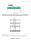
3. The switch manager has to assign different names for each VLAN group at one switch.
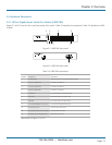
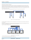
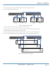
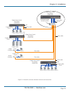
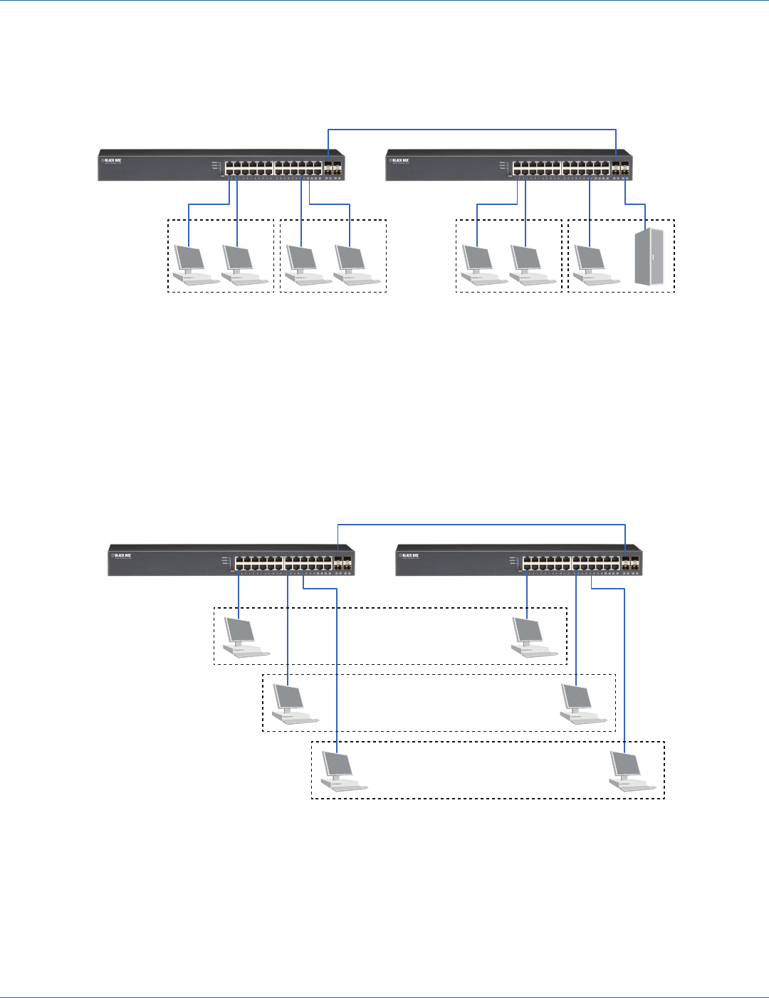
Case 2b: Port-based VLAN (See Figure 3-4).
VLAN 1 VLAN 2 VLAN 3 VLAN 4
Figure 3-4. Port-based VLAN diagram.
1. VLAN1 members cannot access VLAN2, VLAN3, and VLAN4 members.
2. VLAN2 members cannot access VLAN1 and VLAN3 members, but they could access VLAN4 members.
3. VLAN3 members cannot access VLAN1, VLAN2, and VLAN4.
4. VLAN4 members cannot access VLAN1 and VLAN3 members, but they can access VLAN2 members.
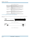
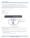
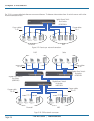
Case 3a: The same VLAN members can be at different switches with the same VID. (See Figure 3-5).
VLAN 1
VLAN 2
VLAN 3
Figure 3-5. Attribute-based VLAN diagram.