


724-746-5500 | blackbox.com
Page 30
Chapter 4: Basic Concepts and Management
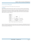
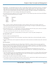
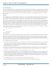
The first three bytes are Organizational Unique Identifier (OUI) codes assigned by IEEE. The last three bytes are the serial number
assigned by the vendor of the network device. All six bytes are stored in non-volatile memory in the device. Their format is shown
in Table 4-3. It is normally written as aa-bb-cc-dd-ee-ff, 12 hexadecimal digits separated by hyphens, in which the
aa-bb-cc is the OUI code and the dd-ee-ff is the serial number assigned by manufacturer.
Table 4-3. Ethernet MAC address.
Bit 47 bit 0
1st byte 2nd byte 3rd byte 4th byte 5th byte 6th byte
OUI code Serial number
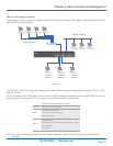
The first bit of the first byte in the Destination address (DA) determines the address to be a Unicast (0) or Multicast frame (1),
known as I/G bit indicating individual (0) or group (1). So the 48-bit address space is divided into two portions, Unicast and
Multicast. The second bit is for a globally-unique (0) or locally-unique address. The globally-unique address is assigned by the
device manufacturer, and the locally-unique address is usually assigned by the administrator. In practice, globally-unique addresses
are always applied.
A unicast address works with a single network interface. With a MAC address, a frame transmitted can be received exactly by the
target interface that the destination MAC points to.
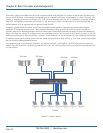
A multicast address works with a group of network devices or network interfaces. In Ethernet, many-to-many connectivity in the
LANs is supported. It provides a way to send a frame to many network devices at a time. When all bits of DA are 1s, it is a
broadcast, which means all network devices except the sender itself can receive the frame and response.
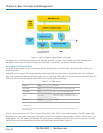
4.3.2 Ethernet Frame Format
There are two major forms of Ethernet frame, type encapsulation and length encapsulation, and both are categorized as
four-frame formats 802.3/802.2 SNAP, 802.3/802.2, Ethernet II, and Netware 802.3 RAW. The basic Ethernet frame format
defined by the IEEE 802.3 standard required for all MAC implementations is explained next.
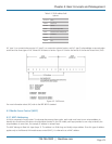
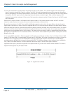
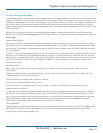
Table 4-4. Ethernet frame structure.
PRE SFD DA SA Type/Length Data Pad bit if any F CS
7 7 6 6 2 46–1500 4
• Preamble (PRE) — The PRE is 7-bytes long with an alternating pattern of ones and zeros used to tell the receiving node that a
frame is coming, and to synchronize the physical receiver with the incoming bit stream. The preamble pattern is:
10101010 10101010 10101010 10101010 10101010 10101010 10101010
• Start-of-frame delimiter (SFD) — The SFD is one-byte long with alternating patterns of ones and zeros, ending with two
consecutive 1-bits. It immediately follows the preamble and uses the last two consecutive 1s bits to indicate that the next bit is
the start of the data packet and the left-most bit in the left-most byte of the destination address. The SFD pattern is 10101011.
• Destination address (DA) — The DA field is used to identify which network device(s) should receive the packet. It is a unique
address. See Section 4.3.1.
• Source addresses (SA) — The SA field indicates the source node. The SA is always an individual address and the left-most bit in
the SA field is always 0.