


724-746-5500 | blackbox.com
Page 18
Chapter 3: Installation
Typical Network Topology in Deployment
A hierarchical network with minimum levels of switches may reduce the timing delay between the server and the client station.
This approach will minimize the number of switches in any one path, lower the possibility of network loops, and improve network
efficiency. If more than two switches are connected in the same network, select one switch as the Level 1 switch and connect all
other switches to it at Level 2. We recommend connecting the Server/Host to the Level 1 switch. This is general advice if no VLAN
or other special requirements apply.
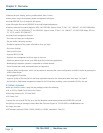
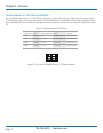
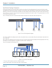
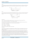
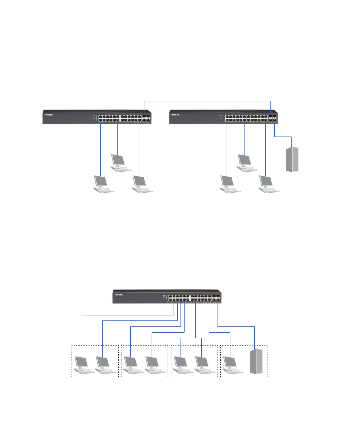
Case 1: All switch ports are in the same local area network. Every port can access each other (see Figure 3-2).
Figure 3-2. No VLAN configuration diagram.
If a VLAN is enabled and configured, each node in the network that can communicate with each other directly is bounded in the
same VLAN area.
Here, VLAN area is defined by what VLAN you are using. The switch supports both port-based VLAN and tag-based VLAN. They
are different in practical deployment, especially in physical location. See Figure 3-3.
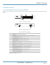
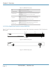
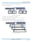
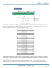
Case 2a: Port-based VLAN (See Figure 3-3).
VLAN 1 VLAN 2 VLAN 3 VLAN 4
Figure 3-3. Port-based VLAN diagram.
1. The same VLAN members cannot be in different switches.
2. Every VLAN member cannot access each other’s VLAN members.