


12-6 BE-0901E-AC-PC• BE-1201B-AC-PC
Chapter 12 Troubleshooting
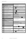
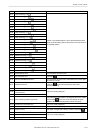
Symptom Measures
The main shaft motor lock error
occurs.
• Enter the encoder signal mode and manually turn the main shaft pulley.
→ If it is abnormally heavy, the main shaft mechanism is faulty.
• Does the main shaft motor rotate at all when the error occurs?
→ If it does not rotate at all, check fuse F1 and F5 on the power supply
PCB in the control box. Refer to the block diagram showing the
cable connections and check to see if connection from the main
shaft motor to the main PCB is proper. Also check connection of
connectors P15 and P16 of the main PCB and connectors P1 and
P2 on the power PCB in the box, and connection from connector
P14 of the main PCB to the 14v terminal of the power transformer.
• Manually turn the main shaft pulley in the encoder signal test mode
and check to see if the stop position signal and encoder signal are
proper.
→ If either of the signals does not change, refer to the block diagram
showing the cable connections and check to see if connection from
the encoder and stop position sensor to the main PCB is proper.
E-A8 frequently occurs.
• In the encoder signal test mode, manually turn the main shaft pulley
and check to see that the stop position signal is correct.
→ If the signal does not change, refer to the cable connection block
diagram and check to see if connection from the stop position
sensor to the main PCB is proper.
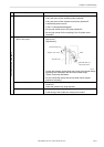
Wiper out error occurs. • Does the wiper remain projected?
→ If the wiper is tangled with a thread, remove it. If the wiper does not
return smoothly, adjust it.
• Enter the solenoid test mode and operate the wiper solenoid. Check
the icon on the panel.
→ If the panel is not changed, check to see if connection from the
wiper sensor to the head PCB is proper. Replace the wiper sensor
with a new one. Replace the head PCB with a new one.
Main shaft rotation speed error
occurs.
• Enter the encoder signal test mode and manually turn the main shaft
pulley.
→ If it is abnormally heavy, the main shaft mechanism is faulty.
• Refer to the block diagram showing the cable connections and check
to see if connection from the main shaft motor to the main PCB is
proper. Also check the connection from connectors P14 of the main
PCB to the 14v terminal of the power transformer.
Exhaust fan motor stops. • Refer to the block diagram showing the cable connections and check
to see if connection of connector P22 of the main PCB in the control
box is proper.
• Check fuse F3 on the power supply PCB.
→ If it is blown, replace it with a new one. If it becomes blown again,
the 24v system circuit is faulty.
ERROR E5 to ERROR FF frequently
occur.
• Replace the main PCB with a new one.
All solenoids of head do not operate. • Refer to the block diagram showing cable connections and check fuse
F2 on the power supply PCB.
→ If it is blown, replace it with a new one. The 60v circuit is faulty if the
fuse is blown immediately after turning on the power even after
replacing the fuse.