


CHAPTER II -2
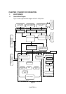
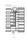
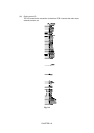
1.2 Main PCB Block Diagram
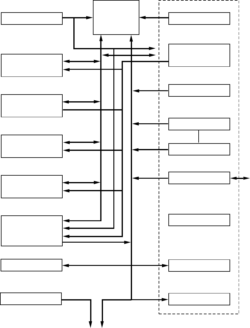
Fig. 2.2 shows the block diagram of the main PCB.
Reset Circuit
Program + Font ROM
(4Mbytes)
RAM
(2Mbytes)
Option RAM (SIMM)
(Max. 32Mbytes)
Optional ROM
(Max. 4Mbytes)
Option Serial I/O
(RS232C & RS422A)
EEPROM (512 x 8bits)
CPU Core
R3041
A S I C
Oscillator (40MHz)
Address Decoder
DRAM Control
Timer
FIFO
DATA EXTENSION
Parallel I/O
Software Support
EEPROM I/O
Engine Control I/O
Motor Driver
To Panel Sensor PCB
BUS
INT
To PC
Fig. 2.2