


ii
2.3 Sensors...................................................................................................................................II-19
2.3.1 Cover Sensor............................................................................................................II-19
2.3.2 Toner Empty Sensor.................................................................................................II-19
2.4 Drum Unit................................................................................................................................II-20
2.4.1 Photosensitive Drum.................................................................................................II-20
2.4.2 Primary Charger........................................................................................................II-20
2.4.3 Developer Roller........................................................................................................II-20
2.4.4 Transfer Roller...........................................................................................................II-20
2.4.5 Cleaner Roller............................................................................................................II-20
2.4.6 Erase Lamp ..............................................................................................................II-20
2.5 Print Process..........................................................................................................................II-20
2.5.1 Charging ...................................................................................................................II-20
2.5.2 Exposure Stage.........................................................................................................II-21
2.5.3 Developing.................................................................................................................II-22
2.5.4 Transfer.....................................................................................................................II-22
2.5.5 Drum Cleaning Stage................................................................................................II-23
2.5.6 Erasing Stage............................................................................................................II-23
2.5.7 Fixing Stage...............................................................................................................II-23
CHAPTER IIIDISASSEMBLY AND REASSEMBLY.......................................III-1
1.SAFETY PRECAUTIONS..................................................................................................III-1
2.DISASSEMBLY FLOW......................................................................................................III-2
3.DISASSEMBLY PROCEDURE.........................................................................................III-3
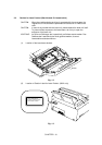
3.1 Drum Unit.................................................................................................................................III-3
3.2 Output Tray ASSY...................................................................................................................III-3
3.3 Top Cover................................................................................................................................III-4
3.4 MP Sheet Feeder 1 ASSY.......................................................................................................III-4
3.5 MP Sheet Feeder 2 ASSY.......................................................................................................III-7
3.6 Under Shoot ASSY..................................................................................................................III-7
3.7 SR PCB / Relay PCB ..............................................................................................................III-9
3.8 Fixing Unit..............................................................................................................................III-10
3.9 Scanner Unit..........................................................................................................................III-14
3.10 Main PCB ASSY....................................................................................................................III-15
3.11 Base Plate ASSY...................................................................................................................III-15
3.12 Driver PCB ASSY..................................................................................................................III-17
3.13 Low-voltage Power Supply PCB ASSY.................................................................................III-18
3.14 High-voltage Power Supply PCB ASSY................................................................................III-19
3.15 Fan Motor ASSY ...................................................................................................................III-19
3.16 Drive Unit...............................................................................................................................III-20
3.17 Main Motor ASSY..................................................................................................................III-21
3.18 Gears and Solenoid...............................................................................................................III-22
3.19 Paper Support........................................................................................................................III-24
3.20 Extension Support Wire.........................................................................................................III-24
4.PACKING........................................................................................................................III-25