


III-19
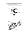
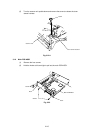
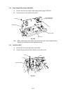
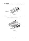
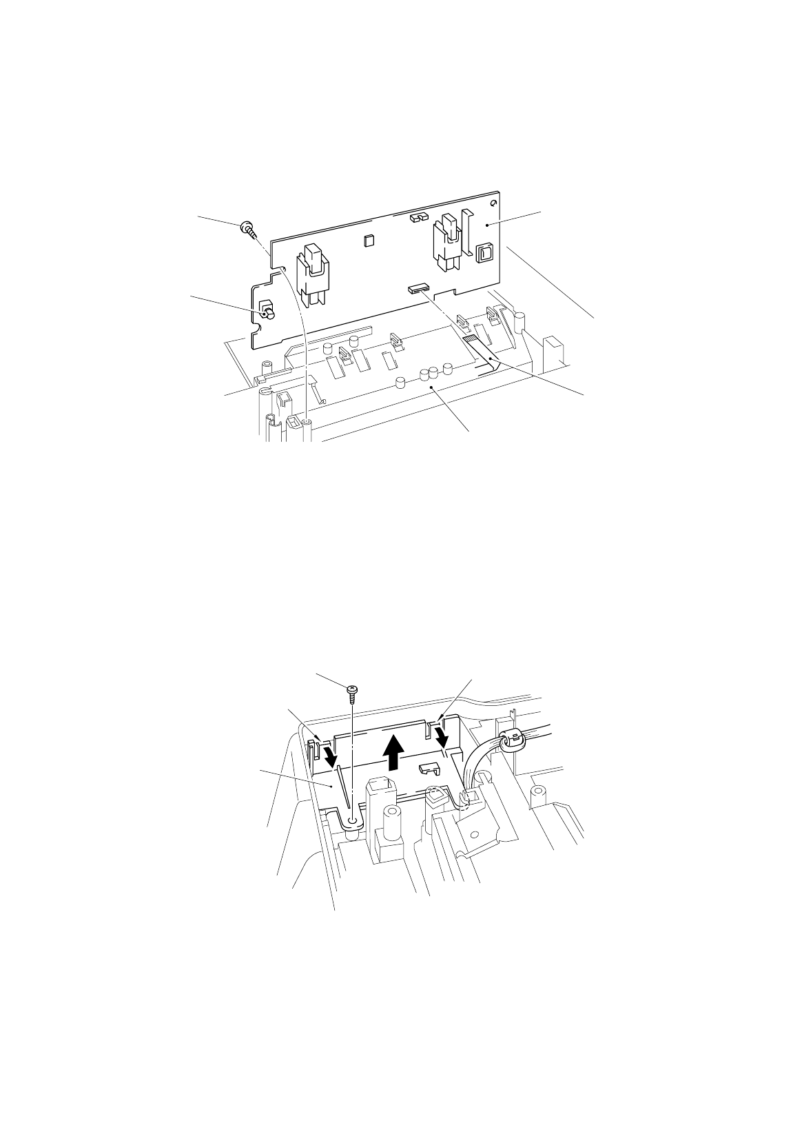
3.14 High-voltage Power Supply PCB ASSY
(1) Remove the screw securing the high-voltage power supply PCB ASSY.
(2) Disconnect the HV flat cable from the PCB.
Fig. 3.30
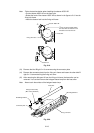
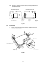
Note: When reassembling, the flat side of the density dial shaft must be aligned with the
flat side of the density dial plastic adjustment cover.
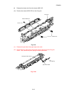
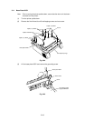
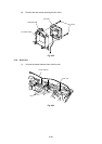
3.15 Fan Motor ASSY
(1) Remove the screw securing the fan motor ASSY.
(2) Release the two hooks of the fan holder from the main cover.
Fig. 3.31
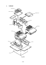
Screw
Density dial
Main cover
HV flat cable
High-voltage power
suppl
y
PCB ASSY
Screw
Fan motor ASSY
Hook
Hook