


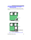
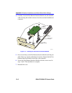
Removing the Chassis Cover
2E48-27R/2E49-27R User’s Guide C-5
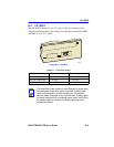
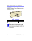
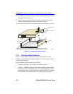
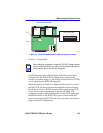
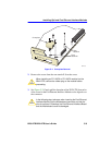
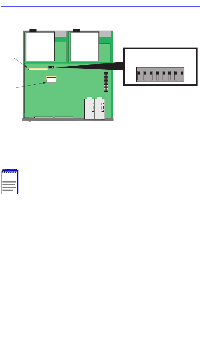
Figure C-2 2E4X-27R Mode Switch Location/Component Layout
• Switch 6 – Forced BootP.
DO NOT attempt a Forced BootP unless a BootP server has been
configured for the 2E4X-27R. The BootP server references the
location of a station acting as a Trivial File Transfer Protocol (TFTP)
server containing the 2E4X-27R image file.
When the position of Switch 6 is changed and the power is cycled to
the 2E4X-27R, the device requests the image file location from the
BootP server and uses TFTP to download the image from the TFTP
server. If one of these requirements is not met, the 2E4X-27R
continues to request either the BootP server or the TFTP server until
the RESET button on the 2E4X-27R is pressed. Once the RESET
button is pressed, the 2E4X-27R resets after one minute and loads the
image stored in FLASH memory.
NOTE
After changing the position of switch 6, DO NOT reapply power
to the chassis until there is a station on the network acting as a
PootP server, which contains the image file.
23141-05
Flash
DRAM
MODE SWITCH BANK
12345678
OFF
ON
FRONT PANEL
TOP VIEW WITHOUT COVER
Primary
Power
Supply
Redundant
Power
Supply