


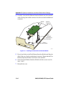
Removing the Chassis Cover
2H23-50R/2H33-37R User’s Guide C-5
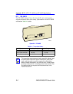
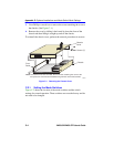
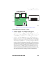
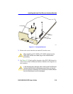
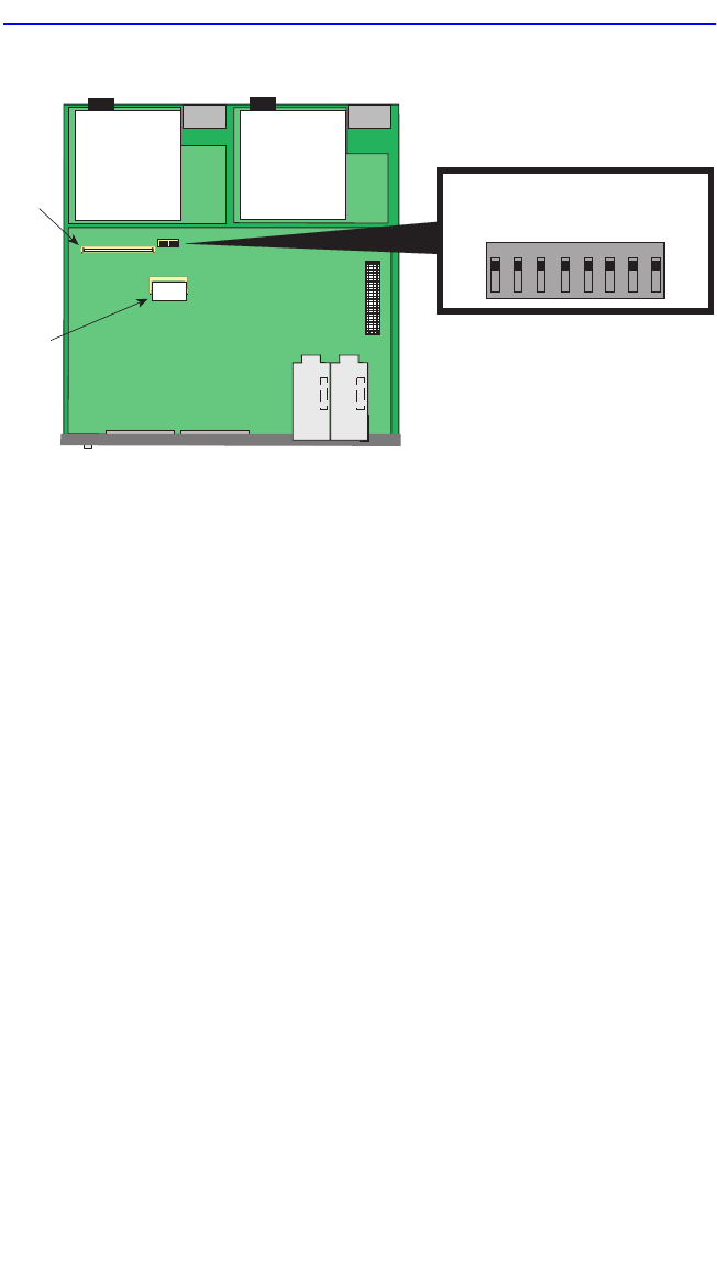
Figure C-2 Mode Switch Location/Component Layout
Switch definitions and positions are as follows:
• Switches 1 through 4 – For Cabletron Systems use only.
• Switch 5 – COM Port Autobaud. The default (OFF) position enables
Autobaud sensing on the COM port for Local Management sessions.
Changing the switch to the ON position disables Autobaud sensing and
sets the COM port to 9600 baud for Local Management sessions.
• Switch 6 – Forced BootP. Do NOT attempt a Forced BootP unless a
BootP server has been configured for the 2H23-50R or 2H33-37R. The
BootP server references the location of a station acting as a Trivial File
Transfer Protocol (TFTP) server containing the image file. When the
position of Switch 6 is changed and the power is cycled to the device,
the device requests the image file location from the BootP server and
uses TFTP to download the image from the TFTP server. If one of
these requirements is not met, the device continues to request either
the BootP server or the TFTP server until the RESET button on the
device is pressed. Once the RESET button is pressed, the device resets
after one minute and loads the image stored in FLASH memory.
22861-0
5
Flash
DRAM
MODE SWITCH BANK
12345678
OFF
ON
FRONT PANEL
TOP VIEW WITHOUT COVER
Primary
Power
Supply
Redundant
Power
Supply