


2-1
Chapter 2
The 9A128-01 Module View
Information displayed in the Module View window; the Chassis Manager window; hub management
functions
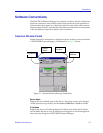
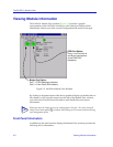
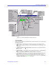
The 9A128-01 Module View window is the main screen that immediately informs
you of the current configuration of your 9A128-01 via a graphical display of the
two bridge ports and the FDDI A and B ports which provide connectivity to the
FNB backplane. (The Module View does not currently provide a display which
reflects the status of the front panel ATM ports.) The Module View window serves
as a single point of access to all other 9A128-01 windows and screens, which are
discussed at length in the following chapters.
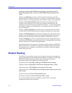
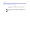
To access the 9A128-01 Module View window, you can either double-click on the
appropriate device icon (as illustrated in Figure 2-1, below), or use the following
menu or toolbar options:
Figure 2-1. 9A128-01 Icon
1. Using the mouse, click on the 9A128-01 icon to be monitored. The icon will be
highlighted. (Note that all MMAC-Plus devices share an icon.)
2. Select M
anage —> Node from the primary window menu bar, or select
from the toolbar; the Module View window will appear.
NOTE
To model your 9A128-01 ATM Access Module as an individual device, you must select
Chassis Manager mode from the window that appears when you launch the icon. Refer to
your Using MMAC-Plus Remote Management Guide for information on how to
access the module view from the MMAC-Plus Chassis View.