


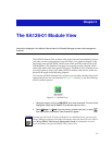

The 9A128-01 Module View
2-2 Viewing Module Information
Viewing Module Information
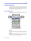
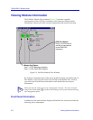
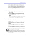
The 9A128-01 Module View window (Figure 2-2) provides a graphic
representation of the 9A128-01, including a color-coded port display which
immediately informs you of the current configuration and status of each port.
Figure 2-2. 9A128-01 Module View Window
By clicking in designated areas of the device graphical display (as detailed later in
this chapter), or by using the menu bar at the top of the Module View window,
you can access all of the menus that lead to more detailed device and port
information.
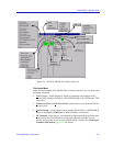
Front Panel Information
In addition to the main interface display, the Module View window provides the
following device information:
TIP
When you move the mouse cursor over a management “hot spot,” the cursor icon will
change into a hand symbol to indicate that clicking in the current location will bring
up a management option.
Bridge Port Status:
Port 1 = FDDI Backplane interface
Port 2 = Front Panel ATM interface
FDDI Port Status:
Ports 1 and 2 are the A
and B port connections
to the FNB FDDI
backplane.