


The 9A128-01 Module View
2-12 Viewing Module Information
FDDI Port Status Color Codes
FDDI port status color codes always reflect the port’s connection status, even
when the LER Estimate port display form has been selected. Under that color
coding scheme:
• CON (Connecting) = yellow
• ACT (Active) = green
• SBY (Standby) = red
• DIS (Disabled) = red
The Chassis Manager Window
Like most networking devices, Cabletron’s devices draw their functionality from
a collection of proprietary MIBs and IETF RFCs. In addition, Cabletron’s newer
intelligent devices – like the 9A128-01 – organize their MIB data into a series of
“components.” A MIB component is a logical grouping of MIB data, and each
group controls a defined set of objects. For example, 9A128-01 bridging
information is organized into its own component; FDDI and ATM information
resides in two separate components, one for each of the 9A128-01’s interfaces.
Note, too, that there is no one-to-one correspondence between MIBs and MIB
components; a single MIB component might contain objects from several different
proprietary MIBs and RFCs.
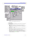
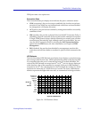
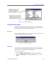
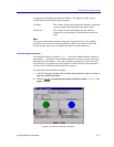
The Chassis Manager window, Figure 2-5, is a read-only window that displays
the MIBs and the MIB components — and, therefore, the functionality —
supported by the currently monitored device.
To view the Chassis Manager window:
1. Click on Help on the far right of the menu bar at the top of the chassis
manager window.
2. Drag down to MIBs Supported, and release.
NOTE
The bridge ports will display Percent Errors when the LER Estimate port status display
is selected. Percent Errors are calculated by the following formula: (ErrorPkts
/(ErrorPkts+ValidPkts))*100, where Error Pkts = IfInErrors + IfOutErrors +
ifInDiscards + ifOutDiscards + ifInUnknownProtos and
ValidPkts = ifInUcastPkts + ifOutUcastPkts + ifInNUcastPkts + ifOutNUcastPkts.