


RF400 Series Spread Spectrum Data Radio/Modems
5
apx
TECHNOLOGIESINC.
CLASS2TRANSFORMER
MODELNO: AP2105W
INPUT: 120VAC60Hz20W
LISTED
2H56
E144634
MADEINCHINA
OUTPUT: 12VDC1.0A
HICKSVILLE,NEWYORK
U
L
R
U
L
R
RS232
DC
Pwr
CS I/O
Pwr/TX
RX
MADE IN USASerial #
Program
Antenna
14320
RF400
Spread Spectrum Radio
This device contains transmitter module:
FCC ID: OUR-9XTREAM
The enclosed device complies with Part 15 of the
FCC Rules.
Operation is subject to the following two conditions:
(1) This device may not cause harmful interference,
and (2) this device must accept any intererence
received, including interference that may cause
undesired operation.
Logan, Utah
SE
DIFF
G
GHL
12
1
AG H LAG HL AG E1AG E2G
34
2
56
3
SE
DIFF
G
GHL
78
4
AG H LAG HL AG E3AG GG
910
5
1112
6
P1GP2GC8C7C6C5C4C3C2C1G12V12V
SDM
5V5VG G
SW 12V
SW 12V CTRL
Logan, Utah
G12V
POWER
IN
CR10X WIRING PANEL
MADE IN USA
WIRING
PANEL NO.
EARTH
GROUND
CS I/O
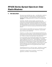
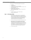
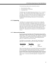
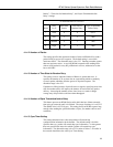
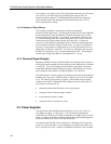
FIGURE 2. RF400 Basic Point-to-Point Network
Step 2 – Set Up Remote RF400
a. Connect an antenna (or antenna cable with yagi or omni directional
antenna attached) to the RF400 antenna jack. The separation between the
base RF400 antenna and the remote RF400 antenna can be any convenient
distance.
b. Connect SC12 serial cable from datalogger CS I/O port to remote RF400
CS I/O port. Current datalogger/wiring panel CS I/O ports apply power to
the remote RF400.
With older dataloggers lacking 12 V on pin 8 (see Table 1), you can
power the RF400 using a Field Power Cable (see above hardware list)
between the datalogger’s 12 V (output) terminals and the RF400’s “DC
Pwr” jack.
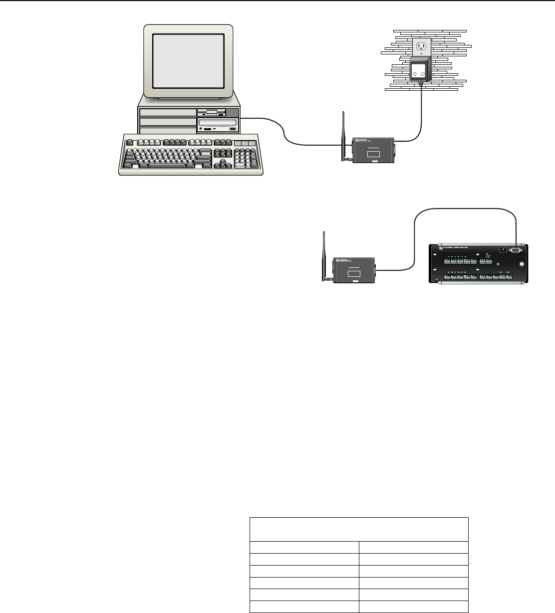
TABLE 1. Lacking 12 V on CS I/O Pin 8
EQUIPMENT SERIAL NUMBER
CR500 < 1765
CR7 700X Bd. < 2779
21X < 13443
CR10 Wiring Panels All (black, gray, silver)
PS512M Power Supply < 1712
When you connect power to the RF400 (through the SC12 cable or the
optional Field Power Cable) you should see the power-up sequence of red
and green LEDs described in Step 1 (assuming datalogger is powered).
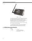
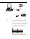
LoggerNet or PC208W
AC Adapter
RS-232
CS I/O
Datalogger CS I/O