


Appendix H. Distance vs. Antenna Gain, Terrain, and Other Factors
H-6
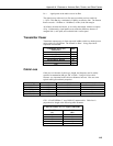
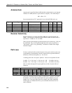
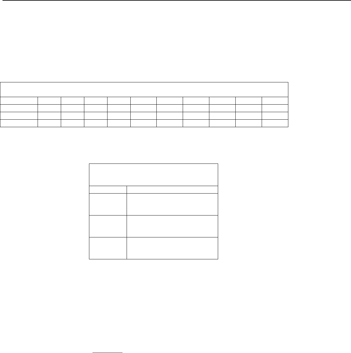
Here is a table which gives calculated path loss (Lp) values at 900 MHz for the
2
nd
, 3
rd
, and 4
th
powers of distance; the equations (for 915 MHz) are:
Lp (2
nd
power) = 95.8 + 20 × log ( d ) dB (d in miles)
Lp (3
rd
power) = 95.8 + 30 × log ( d ) dB (d in miles)
Lp (4
th
power) = 95.8 + 40 × log ( d ) dB (d in miles)
Example calculated Lp values (in dB)
TABLE H-1. 900 MHz Distance vs. Path Loss (Lp in dB) per Three Path Types
Path Type 2 mi. 4 mi. 6 mi. 8 mi. 10 mi. 14 mi. 18 mi. 22 mi. 26 mi. 30 mi.
2
nd
power 102 108 111 114 116 119 121 123 124 125
3
rd
power 105 114 119 123 126 130 133 136 138 140
4
th
power 108 120 127 132 136 142 146 149 152 155
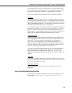
The following table helps select a Path Type in the above “Distance vs. Path
Loss” table to best fit your situation.
TABLE H-2. Path Type vs. Path
Characteristics Selector
Path Type Path Characteristics
2
nd
power Mountaintop to mountaintop
or Tall antenna towers
Line-of-sight
3
rd
power Dominantly line-of-sight
Low antenna heights
Some trees
4
th
power At water’s edge (very reflective)
Across field of grain (reflective)
Lots of Trees (absorptive)
Examples
Some examples will help illustrate the tradeoffs in a link analysis. These
examples will all use the RF400 900 MHz radio, and will use –107 dBm as the
required power level at the radio receiver. This is 3 dB higher than the quoted
sensitivity of –110 dBm, which will give us a 3 dB margin.
Here’s the equation we will use, from the first page:
Pt - Lt + Gt - Lp + Gr - Lr = Pr
Example #1
Antenex FG9023 antennas on each end, 20’ of LMR195 cable on one end, 10’
of LMR195 on the other end, antennas at 10’ height, fairly open terrain with a
few trees. How far can I go?
Pt = 20 dBm
Lt = 20’ x (11.1 dB/100 ft) = 2.22 dB
Gt = Gr = 3 dBd = 5.15 dBi
Lr = 10’ x (11.1 dB/100 ft) = 1.11 dB