RF400 Series Spread Spectrum Data Radio/Modems
8
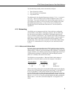
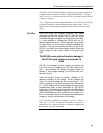
Green LED activity indicates that there is an RF signal being received whose
hopping sequence corresponds to the configured hopping sequence of the
RF400. This does not necessarily mean that the network/radio address of the
received packet corresponds with that of the RF400 (where a neighboring
network exists it is a good idea to choose a unique hopping sequence).
4.1.2 Setup Menu
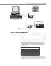
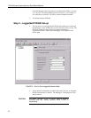
The RF400 has a built-in Setup Menu for configuring active interface, RS-232
properties, network/radio addresses, hopping sequence, power saving (standby)
modes, address masks, and other parameters. The Setup Menu is accessed by
connecting the radio’s RS-232 port to a PC running a terminal program such as
Hyper Terminal
TM
or Procomm
TM
(always 9600 baud, 8-N-1) and pressing the
“Program” button on the RF400 for one second. Changed settings are saved in
flash memory by selecting menu item “5” as you exit the Setup Menu. If left
idle, the Setup Menu will time out 60 seconds after the last received character
and exit without saving any parameter changes with the message “Config
Timeout.” A datalogger can remain connected to the CS I/O port while setting
RF400 parameters on the RS-232 port, although CS I/O communications
would be inactive until exiting the Setup Menu.
4.1.2.1 Auto Sense
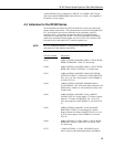
The factory default setting for Active Interface is “Auto Sense.” It is designed
to automatically configure an RF400’s port and radio address mask for
common user situations. When selected, Auto Sense determines whether or
not a datalogger (or PS512M null modem) is connected to the RF400 by
monitoring for 5 V on CS I/O pin 1. If 5 V is present, Auto Sense selects the
RF400’s CS I/O port and a radio address mask appropriate for a remote station.
Not finding 5 V on CS I/O pin 1, Auto Sense selects the RS-232 port and a
radio address mask appropriate for a base station (see Section 4.1.3.1 and
Appendix C for more information on radio address masks).
4.1.2.2 Standby Modes
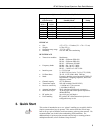
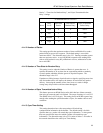
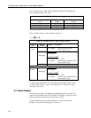
The RF400’s average idle current can be set with the following Standby Modes
(default setting shaded):
TABLE 2. Standard Setup Menu
Duty
Cycle
Standby
Mode
Menu
Selection
Advanced
Standby
Mode
Avg.
Receive
Current
Wake-up
Interval
(red LED
flash interval)
Maximum
Response
Delay*
100% 1 0 < 24 mA 0 sec (constant) 100 mS
17% 2 4 < 4 mA ½ sec 600 mS
4% 3 6 < 2 mA 1 sec 1100 mS
2% 4 7 < .4 mA 8 sec 8100 mS
*Maximum time it takes to get an RF Packet sent and for the other RF400 to respond.


