Appendix L. RF400/RF410 Average Current Drain Calculations
L-9
EXAMPLE #7 (Remote RF400/RF410 in “<0.4 mA, 4 sec Cycle” standby mode )
The RF400/RF410s in this example are configured for the lowest possible
average standby mode current (Advanced Setup Menu selection 7). The same
amount of data are collected as in Example 1, however the frequency of
collection is extended to once an hour.
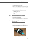
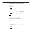
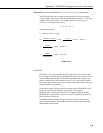
It = Is + Id + Ir + Ii
Calculating each term:
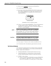
Is = table mA value = 0.4 mA
It ≈ 0.43 mA
SUMMARY
Choosing a lower current standby mode does not always result in an overall
lower average current for the base RF400/RF410 because, by selecting a lower
current standby mode, the base RF400/RF410 must generate a longer “long
header” which involves more transmit time at 73 mA. However, the remote
site will normally benefit from a lower standby mode current since it does not
usually transmit a “long header.”
If the remote station is doing call-backs, then the remote RF400/RF410 must
initiate the connection by sending a “long header” so the remote
RF400/RF410’s average current drain may be higher than that of the base
RF400/RF410. Data collection may be a mixture of scheduled calls and call-
backs (possibly event driven).
As collection intervals become longer, the effects of “time of inactivity to
sleep” and data amount lessen and the average current drain approaches the
stated standby mode current.
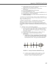
mA 0.001 mA 73
ms 3,600,000
ms 65
mA 73
(ms) T
(ms)] N 2 (ms) 45[
Id =×=×
+
=
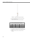
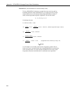
mA 0.0001 mA 24
(ms) 3,600,000
(ms) 20
Ir =×=
mA 0.033 mA 24
(ms) 3,600,000
ms 5000
Ii =×=


