


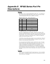


Appendix E. RF400 Series Port Pin Descriptions
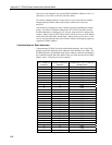
E-2
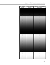
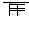
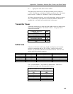
CS I/O CONNECTOR, 9-PIN D-SUB MALE
PIN FUNCTION I/O DESCRIPTION
1 5V I Sources 5 VDC to power peripherals
2 GND GND for pin 1 and signals
3 Ring O Raised by modem to put datalogger
into telecommunications mode
4 RX O Serial data receive line
5 Modem Enable I Raised when datalogger determines
that associated modem raised the
ring line
6 Synchronous Device
Enable
I Used by datalogger to address
synchronous devices; can be used as
a printer enable
7 CLK/Handshake I/O Used by datalogger with SDE and
TX lines to transfer data to
synchronous devices
8 12V supplied by
datalogger
PWR Sources 12 VDC to power
peripherals
9 TX I Serial data transmit line
I = Signal Into the RF400, 0 = Signal Out of the RF400